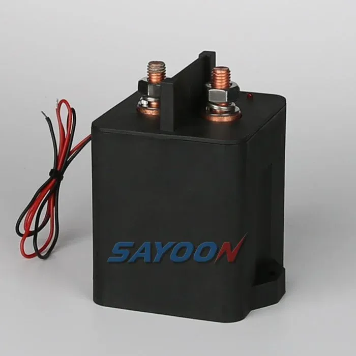
If you want to improve your electrical systems, you need to learn how to wire a basic contactor properly. A basic contactor is an electromechanical switch that turns your power circuit on or off. Read this guide covering the various aspects of how you wire a basic contactor wiring step by step so it will be easy to understand – even if you are new to the subject.
What is Basic Contactor Wiring?
“Basic contactor wiring” is how to connect a contactor to the circuit that will control electric devices, including lights and motors. The implementation of this method (basic contactor wiring) allows for remote control and/or automation; therefore, it is highly valuable in both industrial and commercial applications. To ensure safety and proper function, understanding the correct way to wire a contactor or contactors is important.
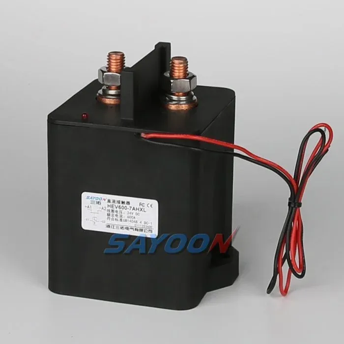
Working Principle of Basic Contactor Wiring
The operation of a contactor is simple but intriguing; when voltage is provided to a coil in a contactor, it forms an electromagnetic field which takes hold of a mobile armature, moving the armature into position with respect to the contactor to close the electrical circuit supplying or connecting the electrical supply to a load (for example, electric motor). Once the voltage is removed from the coil, the magnetic field dissipates and the armature returns to its original or resting position, hence opening or creating an open circuit (broken contact), thereby stopping the flow of electrical energy. This method of operation allows for the safe and effective control of electrical power at high loads and voltages.
Step-by-Step Contactor Wiring Tutorial for Beginners
Let’s break down the process of basic contactor wiring into manageable steps:
Step 1: Gather Your Tools and Components
Check that you have an appropriate amount of equipment prior to starting your new wiring project. Required tools include: wire strippers; driver; plugs (or tape) for your voltage tester; and the contactor itself. You will also need gauge of wire based on your load requirements.
Step 2: Understand the Terminal Layout
Learn the layout of the contactor’s terminals. Generally, there are three parts: the coil terminals which will usually be labelled A1 and A2, and the load release terminals which will usually be labelled L1, L2 and L3 in the case of three-phase systems.
Step 3: Connect the Coil
Conclude by connecting the coil leads (A1 and A2) to your control panel. Check that the control panel voltage matches the required coil voltage. Safety should always be a consideration; be sure to shut down the power supply prior to connecting the leads.
Step 4: Wire the Load
The final step requires you to connect your load to the ‘load’ terminals. For a single-phase load, you’ll connect your incoming power to L1, while L2 and/or L3 can accommodate additional loads or remain vacant if you have no additional loads. Each of the connections must be adequately connected so there will be no electrical failures.
Step 5: Test Your Wiring
After completing the wiring, you should verify that the connections are both secure and accurate. Once you have verified that the wiring is done properly you can turn the power back on and test the operation of the contactor. Using a voltmeter, you should be able to see if the load is activated when the coil is energized.
Common Mistakes to Avoid
Although connecting together a basic contactor wiring is a rather simple task to accomplish, beginners will often run into problems that could be avoided.
Below are several examples of typical mistakes made when wiring a contactor.
– Small wire sizes: Check that the wires you’re using are rated for the load they will be controlling to eliminate the possibility of overheating or failure.
– Failing to match the control coil voltage could lead to unnecessary loss of life.
8. Agyung to tight connections: Loose connections may result in electrical fires and arcing. So remember, always check all your electrical connections are tight enough to avoid any potential risks.
FAQs
What is basic contactor wiring?
The process of connecting a contactor to an electrical device for the purpose of automation and safety when using high amounts of electrical power is called the wiring of a contactor.
What is the working principle of basic contactor wiring?
The electromagnetic system inside the contactor creates an electromagnetic force when the coil is energized, which causes the contactor’s contacts to close and connect power to whatever load that is connected to its contacts.
What tools do I need for basic contactor wiring?
You will need a wire stripper, screwdriver, voltage tester, and gauge appropriate for the size of your load.
By doing a successful job at understanding basic contactor wiring basics, you will greatly improve your electrical control abilities. Newbies can do some electrical work with more confidence by taking into consideration the steps outlined above and using proper safety procedures while completing these types of projects. Always make safety a priority, verify that your connections are correct, and consult a professional if you are unsure that your work is safe.