A pre magnetic contactor in EV vocabulary is the precharge (pre-charging) contactor: a small sealed HV DC contactor that closes first through a precharge path so the DC-link capacitance charges under controlled current, and only then does the main contactor close — limiting inrush that would otherwise erode or weld main contacts, with device choices audited against published HEV series fields.
This explainer is for EV powertrain and BMS engineers who inherited the term from supplier lists and need it mapped onto real precharge design. The device family behind it on this site is the HEV series HV DC contactors line, and every model claim below quotes a published table row.
Part 1. What does pre magnetic contactor mean in EV precharge vocabulary?
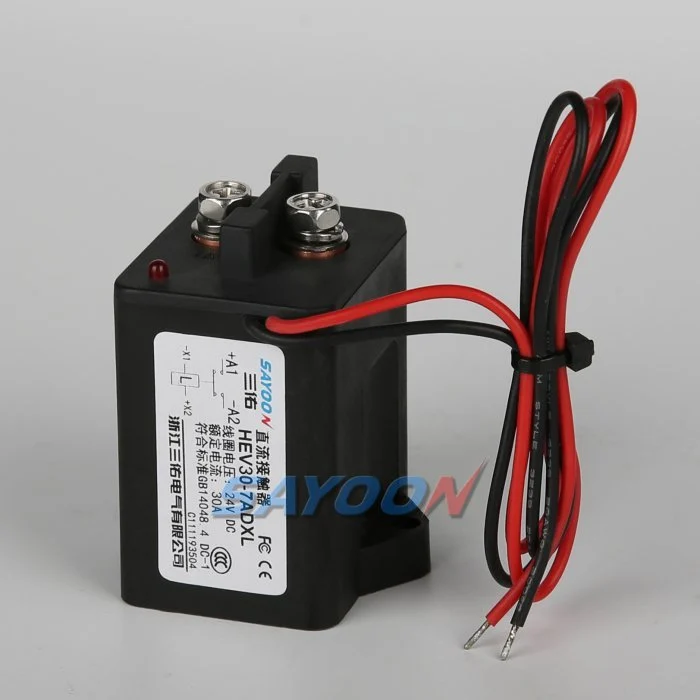
The phrase pre magnetic contactor appears in supplier word lists and translated catalogs, and it confuses teams because magnetic also describes latching architectures. In precharge context the mapping is simple: it is the pre-charging contactor — the small contactor that conducts first, before the main path.
SAYOON publishes that mapping on its application pages, where Pre-charging Contactors are listed for pre-charge control before main circuit connection. So treat the term as a role name in the connect sequence, not a separate device technology.
| Term seen in lists | Role in the EV circuit | Where it is published |
|---|---|---|
| Pre magnetic / pre-charging contactor | Closes first through a resistor path to charge the DC link | Solution-page product mapping |
| Main contactor | Carries the traction or bus current after charge | HEV / SEV main-path SKUs |
| Magnetic holding (latching) contactor | Hold-power-saving architecture, a different topic | CZW-K family pages |
Part 2. Why does inrush current drive precharge design in EV DC links?
Inverter front-ends present large discharged capacitances to the battery at connect time. Closing one contactor straight into that load draws a current spike limited mostly by loop resistance — the classic capacitive inrush current problem.
Field stories repeat the consequence: eroded or welded main contacts after repeated hard connects. A precharge branch tames the spike by charging the link through a resistor first, so the main contactor closes across a small voltage difference instead of a discharged capacitor.
| Design fact | Consequence without precharge | Precharge answer |
|---|---|---|
| DC link starts discharged | Connect spike stresses contacts | Charge link before main close |
| Spike limited only by loop resistance | Erosion, welding, nuisance faults | Resistor-limited charge current |
| Repeated connects per day | Cumulative contact damage | Controlled, repeatable sequence |
Part 3. How does a precharge contactor work beside the main contactor?
The working pattern is a three-step sequence owned by the BMS or vehicle controller. The step ordering details are covered in the live precharge and main connect sequencing basics guide, so this article keeps the device view.
- Close the negative main and the precharge contactor; current flows through the precharge resistor.
- Monitor link voltage until the controller’s charge criterion is met.
- Close the positive main contactor, then open the precharge branch, which returns to rest.
Two device consequences follow. The precharge contactor sees a lower, resistor-limited current but must match the bus voltage class, and it accumulates one operation per connect cycle, so its published life rows matter as much as its current line. The distinct duty of main devices is compared in EV contactor versus standard DC contactor.
Part 4. Which published HEV fields matter for precharge and inrush duty?
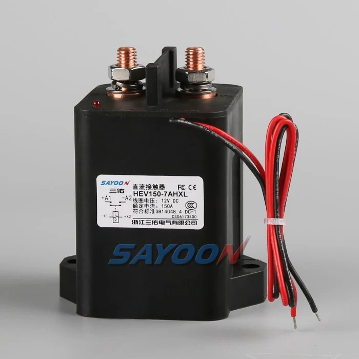
The HEV code system publishes contact rated voltage classes of 1 -200V; 7 -1000V, which is the first field to match against the bus. Beyond that, the small and mid classes publish the rows a precharge design audits.
| Published field | HEV30 | HEV100 | HEV150 |
|---|---|---|---|
| Contact voltage classes | 200 V, 1000 V | 200 V, 1000 V | 200 V, 1000 V |
| Load current (DC-1) | 30 A | 100 A | 150 A |
| Coil power line | D: 3–7; H: Start 3–7, Keep 0.5–1.5 | D: 4–10; H: Start 4–10, Keep 0.5–2 | D: 4–10; H: Start 4–10, Keep 0.5–2 |
| Inrush time (max) | 130 ms | 130 ms | 130 ms |
| Protection / ambient | IP68 / -40 to +85 C | IP68 / -40 to +85 C | IP68 / -40 to +85 C |
| Electrical / mechanical life | 20,000 / 300,000 times | 20,000 / 300,000 times | 20,000 / 300,000 times |
Read the inrush time row as a published device boundary for abnormal current windows, not as a license to skip the resistor. The charge profile itself is a system calculation owned by the designer.
Part 5. Which option codes relate to precharge and capacitive loads?
Published model-implication tables carry two option codes worth knowing in precharge work. They are code lines, not sized components, so quote them as ordering vocabulary only.
| Published option code | Where it appears | What the page says |
|---|---|---|
| R | CZW family code tables | With pre-charged resistance |
| V | HEV / SEV code tables | With capacitive type load |
| N | HEV / SEV code tables | No polarity |
Ordering discipline follows: if a design assumes any of those options, the RFQ must spell the full code and ask engineering to confirm the delivered configuration, because the public tables list the codes without resistor values or capacitance limits.
Part 6. Which SAYOON models anchor a precharge RFQ under the HEV pillar?
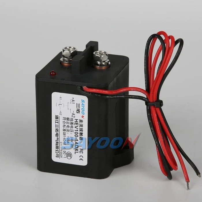
Product recommendation: anchor the precharge branch on the HEV30 high voltage epoxy resin sealed DC contactor when the branch fits its published 30 A DC-1 class and the bus matches a published 200 V or 1000 V code. Pair it with a main-path device such as the HEV100 high voltage epoxy resin sealed DC contactor audited on its own rows.
Why not other lines without review: HEV150 and larger classes belong on main paths, not precharge branches, in most architectures; SEV codes suit programs standardized on that family; and no SKU should be assumed to contain an internal precharge resistor beyond its published option-code line.
Fit Boundary: a precharge contactor is not a main traction device, not a replacement for a correctly engineered precharge resistor, and not valid outside its published voltage class and current rows. Wider disconnect-path selection logic lives in HV contactor selection for battery disconnect.
To confirm a pairing, send your DC-link and precharge notes with bus voltage class, capacitance, branch current, and coil preferences.
Part 7. What precharge design mistakes damage EV DC paths?
- Skipping the precharge branch entirely and hard-connecting the main contactor into a discharged link.
- Choosing the precharge device by current only and missing the 200 V vs 1000 V class code.
- Assuming a contactor code with option R defines resistor ohms and watts — the tables publish the code, not values.
- Ignoring the operation count precharge devices accumulate on every connect cycle.
- Treating the published inrush time row as permission to remove the resistor.
- Leaving the precharge branch closed in parallel with the main path after connect.
- Reusing magnetic holding vocabulary for precharge duty and ordering the wrong architecture.
References
FAQs
What is a pre magnetic contactor?
It is list-vocabulary for the pre-charging contactor: the small HV DC contactor that closes first through a resistor path so the DC-link capacitance charges before the main contactor carries the bus.
What does a precharge contactor do in an EV?
It limits connect inrush. Closing it through the precharge resistor charges the inverter DC link under controlled current, so the main contactor later closes across a small voltage difference.
What happens if precharge is skipped or fails?
The main contactor connects a discharged capacitance directly to the battery, and the resulting spike erodes or welds contacts over repeated cycles — the most common field failure story in this topic.
How is the precharge contactor different from the main contactor?
The precharge device conducts briefly through a resistor at lower current but full bus voltage class; the main device carries continuous traction or bus current. Each is audited on its own published rows.
Which HEV fields should a precharge RFQ quote?
Quote the contact voltage class code (200 V or 1000 V), DC-1 current, coil power line, inrush time row, IP and ambient rows, and the life figures — all from the exact SKU page.
Does SAYOON publish precharge resistor values?
No. Public code tables list option R as with pre-charged resistance and option V as with capacitive type load, without resistor values, so RFQs must ask engineering to confirm delivered configurations.
Where should an EV precharge shortlist start on this site?
Start at the HEV series pillar, match the published voltage class and current rows, then send the DC-link details through the contact page for confirmation.





