The choice of DC contactor vs solid state relay depends on switching frequency, thermal limits, off-state behavior and the required disconnect function. A contactor opens mechanical contacts; a DC-rated solid-state relay switches through semiconductor devices. Frequent silent switching can favor an SSR, while an infrequently operated mechanical boundary can favor a contactor. Neither choice automatically supplies short-circuit protection or an approved maintenance isolator. Compare the complete installed system, not two headline current ratings.
This guide addresses high-current DC load switching for equipment builders. It compares an industrial SSR module with a contactor, rather than designing a discrete MOSFET battery disconnect. The deciding questions are how often the load switches, how much heat the assembly must remove, what current remains when commanded off, and how failures are detected and contained.
Start by specifying the output circuit, not the control input
A relay advertised with a DC control input is not necessarily suitable for a DC load. Identify both sides separately: input voltage and driver requirements on the control side, and voltage, current, device technology and permitted direction on the output side. Record the full part number and the manufacturer’s output-circuit specification before interpreting a product title.
The University of Texas at Austin control-systems chapter discusses semiconductor output switching and the parameters needed to select an SSR. AC-output designs using devices that depend on current crossing zero cannot be assumed to turn off a continuous DC load. For DC service, obtain explicit DC output ratings and the intended turn-off behavior. Do not attempt to establish compatibility by testing an unknown module on an energized high-current bus.
A contactor also needs explicit DC switching evidence. An AC rating cannot simply be transferred to a DC circuit at the same voltage. Specify current direction and the applicable circuit characteristics, including inductance where relevant. For both technologies, carry capability, making duty and fault behavior are separate questions.
Let the switching schedule define the comparison
Write the expected events over a working shift or operating cycle. An SSR may suit frequent load control because semiconductor switching avoids mechanical contact wear. However, the required repetition rate still has to fit the module’s thermal and transient limits. A contactor can serve a less frequently operated connect-disconnect boundary when its documented electrical endurance matches the duty.
Distinguish duty cycling from pulse-width modulation. Rapid PWM control is a power-electronics function requiring appropriate devices, drivers and protection; an arbitrary industrial SSR is not automatically a suitable PWM stage. Similarly, repeatedly commanding a contactor at a rate beyond its documentation can produce unacceptable heating and wear.
Consider noise and service expectations. Mechanical motion can produce an audible operating sound. Semiconductor switching can reduce that source of noise, but cooling fans and other system parts may remain audible. Choose based on the assembled machine’s requirements rather than a claim that one technology makes an entire machine silent.
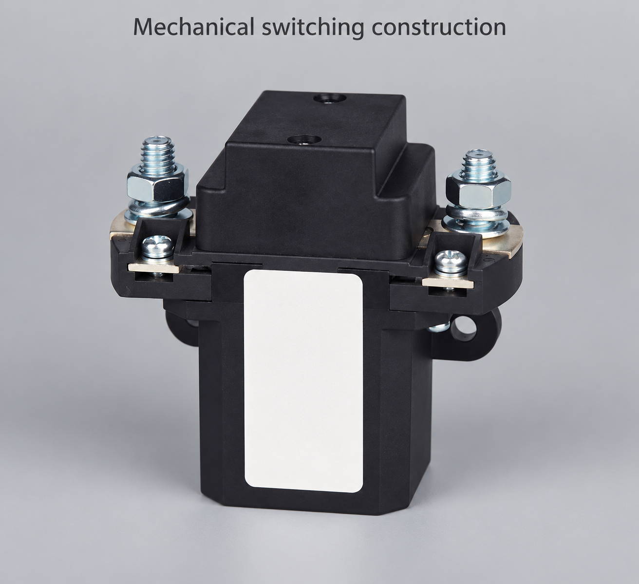
Compare installed losses and the heat-removal path
Both technologies produce heat. A contactor has contact and termination losses plus coil consumption, depending on its control arrangement. An SSR has semiconductor conduction losses and, where switching frequently, switching losses. The headline current value is meaningful only with its stated cooling conditions. Compare enclosure temperature, conductor arrangement and cooling requirements alongside the electrical duty.
MIT OpenCourseWare’s lecture on switching losses and snubbers explains conduction and switching loss analysis. For an output specified by on-state resistance, a simplified conduction estimate is P = I²R, with current in amperes, resistance in ohms and loss in watts. For an output specified by voltage drop, use the applicable voltage-current data rather than assuming a fixed resistance.
For illustration only, an assumed resistance of 0.002 ohm at 100 A gives 20 W using I²R. Those inputs are hypothetical, not ratings for an SSR or Sayoon contactor. The result describes estimated conduction loss at that operating point, not an allowable current. Actual resistance changes with conditions, and terminations, coil power or switching losses may add heat.
For an SSR, trace the path from the switching device through its mounting interface and heat sink to ambient air. Include interface preparation, mounting instructions and airflow. For a contactor, inspect the terminal and conductor arrangement as well as the body. Validate the final enclosure; a comfortable bench temperature is not evidence for an enclosed machine operating beside other heat sources.
Define what commanded off must mean
An SSR can have off-state leakage, and connected circuits may show a measurable voltage even when the control input is off. Obtain leakage data for the exact device and test conditions. Determine whether that current can keep a small load active, charge a capacitor or confuse a diagnostic measurement. Do not treat a voltage reading alone as proof of useful available power or of complete disconnection.
A mechanical contactor creates a contact gap when it operates as intended, but the assembly may still have parallel paths, stored energy or suppression components. Welded contacts can defeat the intended opening. A control command, coil signal or indicator is therefore not independent evidence that every relevant conductor is deenergized.
Optical isolation in an SSR control circuit concerns the relationship between its input and output. It does not automatically make the switched output an approved maintenance isolation boundary. 29 CFR 1910.333 addresses electrical work practices within its scope. Apply the relevant jurisdictional rules, isolate all required sources and verify the safe state through the approved procedure.
Use a comparison table tied to real acceptance evidence
This qualitative table compares typical design considerations, not universal product capabilities. Exact ratings and allowable functions come from the selected device documents and the system assessment. A blank evidence item remains an open engineering question, regardless of which technology appears preferable.
| Decision | DC contactor review | DC-rated SSR review |
|---|---|---|
| Frequent switching | Check electrical endurance at actual load duty | Check repetition rate, transient stress and heating |
| Installed current | Verify contacts, joints, coil and enclosure temperature | Verify loss, heat sink, interface and enclosure temperature |
| Commanded off | Assess welded contacts and parallel paths | Assess leakage, blocking behavior and shorted-output faults |
| DC compatibility | Request DC make/break evidence and directional limits | Confirm explicitly DC-rated output technology |
| Control power | Check pickup, hold, release and suppression | Check input threshold, driver and loss-of-control behavior |
| Fault protection | Establish protective-device coordination | Establish semiconductor protection and fault containment |
| Service isolation | Confirm allowed function of the complete device | Do not equate input isolation with an output disconnect |
| Installation cost | Include driver, conductors, mounting and maintenance | Include cooling, interface, protection and diagnostics |
Review fault behavior and protective coordination
A semiconductor output can fail shorted, and mechanical contacts can weld. Neither “no moving parts” nor an opening mechanism guarantees a safe failure state. Record credible faults, how the controller detects them and what independently removes energy when required. Define the response when the main switch disagrees with feedback.
For inductive loads, identify how stored energy is managed when current is interrupted. The appropriate suppression depends on the circuit and allowable voltage. A generic diode or snubber copied from an unrelated circuit can change release timing or leave the wrong path conducting. Use approved component and load documentation rather than prescribing one universal suppression arrangement.
Protective devices must coordinate with the actual switch. Ask for the relevant short-circuit withstand, protective-device conditions and fault-clearing evidence. A quoted peak-current value does not establish fault protection for every battery or converter. Include the source’s available energy and the complete protection architecture in the assessment.
Validate the proposed module or contactor in its assembly
Test the normal switching schedule, worst permitted thermal condition, control-input loss, relevant transient events and diagnostic behavior. Write acceptance criteria before testing. For an SSR, include the off-state circuit behavior and cooling arrangement. For a contactor, include operation at the documented control-supply limits and the actual conductor installation.
Measure conditions that can reveal different failure mechanisms: terminal temperatures, control-supply voltage, load current and confirmed output state. Keep measurement uncertainty and sensor location in the record. A low measured current during one test does not prove capability at the maximum requirement, and an unloaded operating check does not verify interruption duty.
Compare the complete quotation and document the choice
Ask each supplier to quote the switch together with required driver, cooling, protection, mounting and diagnostic provisions. Record technical exclusions and the evidence still required. An inexpensive SSR module may need a substantial heat sink, while a contactor may need a driver or a specific coil option. Compare installed cost and supported duty, not unit price alone.
Use the QZJ100A product page to begin a mechanical-device discussion, and the wiring and comparison guides for wider context. The contact-resistance guide and ambient-temperature guide support installation questions. For a discrete transistor battery-disconnect architecture, use the separate contactor versus MOSFET guide; that is a different design comparison.
Further learning: mechanical contactor operation
Electrician U explains how a mechanical contactor operates. This background helps distinguish moving contacts from an electronic switching output. It does not qualify an SSR, establish DC interruption limits or replace the thermal and protection assessment.

Watch the educational contactor explanation.
Frequently asked questions
Can an AC-output SSR switch a DC load?
Do not assume so. The output technology and turn-off behavior must explicitly support DC service. A DC control-input rating says nothing by itself about DC output compatibility.
Is an SSR always cooler than a contactor?
No. Compare conduction and switching losses, cooling requirements and installed conditions. The full assembly may need a heat sink, while a contactor also has contact, termination and coil losses.
Does an SSR provide zero current when switched off?
Not necessarily. Obtain the exact off-state leakage and blocking data, and assess its effect on the connected load and diagnostics. Commanded off does not establish a safe maintenance boundary.
Which option is better for high-current equipment?
There is no universal winner. Frequent switching can favor an appropriately rated SSR, while an infrequent mechanical switching boundary can favor a contactor. Confirm thermal limits, failure response and protection for the specific installation.





