A contactor mirror contact is a specifically documented feedback contact with a defined relationship to the contactor’s main contacts. An ordinary auxiliary contact must not be assumed to provide that relationship merely because it is normally closed or follows the armature. For a safety-related feedback circuit, verify the exact contactor, auxiliary block, mounting arrangement, applicable standard, and manufacturer’s declaration. Mirror contact, mechanically linked relay contacts, and ordinary position feedback are different descriptions. None of them alone proves absence of hazardous voltage or establishes the performance of a complete safety function.
Start with the failure the system must detect
Consider the question behind a feedback requirement: what should happen if a commanded-open main contact remains closed? A control system might need to prevent restart, raise a diagnostic fault, or bring another device into a defined state. Write that intended response before choosing a contact label. Otherwise a familiar normally closed symbol may be accepted without evidence that it reports the relevant failure.
Separate normal sequence monitoring from the safety function. Normal monitoring can confirm that a signal changed after a command. A safety-related design must also consider faults, diagnostic coverage, architecture, common causes, timing, and verification. The contact arrangement is one component of that work. A procurement statement saying auxiliary contact included is therefore insufficient when the requirement actually concerns a documented relationship under specified abnormal conditions.
What an ordinary auxiliary contact tells you
An ordinary auxiliary contact switches a relatively small control or indication circuit according to its documented operation. It may support a status lamp, a controller input, seal-in logic, or an interlock. Its normal state, electrical duty, switching capability, and timing belong to the exact product and configuration. Physical movement with the contactor does not automatically make every feedback claim valid.
A signal can also be wrong because of a broken conductor, a short, a connector fault, an unsuitable input current, or an incorrect terminal assignment. Those issues remain relevant even when the contact itself operates as intended. Read the existing auxiliary-load and troubleshooting guides for those electrical-interface questions. This article focuses on what documented contact architecture does, and does not, establish for feedback selection.

What makes the mirror-contact question different
The mirror-contact concept concerns a specified relationship between the relevant main contacts and a normally closed auxiliary contact. IEC 60947-4-1 is the applicable standards family for the contactor concept. Use the edition and requirements adopted for the project, and obtain the manufacturer’s statement identifying the exact device and arrangement. Do not infer compliance from a generic standards reference in a catalog footer.
Public manufacturer explanations distinguish this concept from mechanically linked contact elements in control devices. That distinction is useful when reviewing terminology, but another manufacturer’s declaration does not establish a Sayoon product’s capability. A test report, declaration, or approved drawing must identify the proposed ordering code and any required auxiliary block. If the documentation does not confirm the requested property, the candidate remains unverified for that feedback role.
Do not equate mirror contacts with mechanically linked relay contacts
A document can describe mechanically linked or positively driven contact elements within a control relay. Another can describe mirror contact characteristics of a power contactor. Similar everyday wording does not make the scopes interchangeable. Ask which contacts have the declared relationship and which standard or manufacturer’s definition is being applied.
Avoid shortening all these descriptions to safety contact in a purchase order. That phrase can conceal the exact requirement. Record the intended main contacts, feedback terminals, normally open or normally closed behavior, approved accessories, and relevant declaration. If a supplier proposes a different contact architecture, have the responsible designer review whether it meets the original system requirement rather than treating the name as proof of equivalence.
Check the complete contactor and accessory combination
Some auxiliary contacts are integrated; others are fitted as front or side accessories. The documented property may depend on the mounting position and permitted combination. A block with the right number of terminals is not necessarily an approved substitute. Obtain the current installation instructions and confirm that the actual assembly matches them.
Record both the contactor code and the accessory code. Include the revision, mounting location, and any restrictions on additional accessories. A service replacement that retains the main contactor but changes the auxiliary block can alter the evidence supporting the feedback arrangement. Likewise, a mechanically fitting block from another family cannot inherit the original declaration. Keep that identity information in the spare-parts record as well as the design file.
Define the feedback truth table
For each operating state, list the command, expected main-path condition, expected feedback state, and controller response when the observations disagree. Include power-up, normal run, stop, restart and service states. State which measurement is available and what it actually proves. A feedback input and a voltage measurement answer related but different questions.
The table should distinguish a delayed transition from a persistent disagreement. Timing comes from the documented devices and the validated system sequence; there is no universal delay suitable for all contactors. State whether the controller uses an input test function, how it recognizes wiring faults, and how it prevents an unsafe automatic restart. The responsible safety designer must decide what the architecture requires.
Selection evidence checklist
The following comparison is qualitative. It does not declare any illustrated Sayoon product to have mirror contacts or assign a safety rating. Use it to request missing evidence and to prevent a general auxiliary-contact description from being substituted for the required architecture.
| Review item | Evidence | Decision |
|---|---|---|
| Ordinary auxiliary | Normal state, duty and timing | Do not infer mirror characteristics |
| Mirror arrangement | Exact declared main/auxiliary relationship | Match the specified combination |
| Mechanically linked relay contacts | Device scope and relevant declaration | Do not interchange terminology |
| Accessory replacement | Contactor code, block code and position | Revalidate changed combinations |
| Controller feedback | Input behavior and fault-response design | Review the complete function |
| Safe servicing | Approved energy-isolation procedure | Do not use feedback as absence-of-voltage proof |
Keep electrical ratings in the review
A documented mechanical relationship does not remove the need to match the feedback contact to the input circuit. Review the operational voltage, current, minimum applicable load where stated, switching duty, insulation, terminal connections and environmental conditions. A controller input drawing little current can create a different interface question from switching a relay coil.
Check the input threshold, diagnostic pulses, leakage paths and return reference. Do not cure an input mismatch with an improvised resistor or lamp without reviewing its effect on diagnostics and fault detection. The load-rating article handles the numerical interface work; this review establishes which contact arrangement is being purchased and what supporting evidence the control design can rely on.
Validate the fault response through an approved method
Plan how the complete system will demonstrate its required response to relevant failures. Use the manufacturer’s allowed verification methods and the project’s safety-validation plan. Do not intentionally weld contacts or improvise hazardous high-current tests as a field demonstration. A controlled simulation of a signal fault has different limits from a component test and must be identified correctly in the record.
Retain the command traces, feedback observations, diagnostic states, reset behavior and final disposition. Explain which faults the method represents and which it does not. A successful normal open-and-close cycle proves only the behavior observed in that cycle. It cannot, by itself, establish the documented abnormal-condition relationship or the achieved performance level of the full safety function.
Understand the limits of a closed feedback contact
A reported open command, a changed feedback input and zero load current do not automatically prove that every accessible conductor is de-energized. Another source, stored energy, a precharge path or a measurement fault may remain relevant. Follow the authorized isolation and absence-of-voltage procedure before work on the main circuit.
This boundary is important for service instructions. The operator display may summarize the machine state for normal use, while the electrical work procedure needs additional checks. Do not rewrite a feedback signal description as safe to touch. Keep control diagnostics, energy isolation and verification of the work area as separate requirements with their own evidence.
Control replacement and purchasing language
A useful purchase specification identifies the intended contact architecture, the required evidence, the accepted combination, and the drawing revision. It also states which substitutions require review. Avoid requesting only a normally closed spare with matching dimensions: that can satisfy the terminal count while losing the property the feedback design depends on.
For incoming inspection, confirm identity, markings, accessory fit and document revision against the approved record. A visual inspection can reveal the wrong block, but it cannot establish an undocumented internal relationship. If a declaration covers only another variant, ask for clarification before release. Record the unresolved requirement rather than filling it with an assumption based on appearance or a similar product name.
Product reference and business scope
The CZWH100A 1NO1NC DC contactor is the real Sayoon construction reference illustrated here. Its visible terminals and listed contact arrangement do not establish mirror-contact performance. This article does not claim that this model is a safety contactor or that it satisfies a particular feedback function. Request the exact documentation for the proposed product and application.
Send the intended circuit role, contact arrangement, input details, fault-response requirements and requested evidence with the inquiry. If a documented mirror-contact arrangement is essential, state that requirement explicitly. The supplier can then confirm applicability or identify a requirement it cannot substantiate. A transparent answer is more useful than accepting a generic claim of reliable auxiliary feedback.
Educational video
The Electrician U introduction explains basic contactor operation and the difference between the coil and main circuit. It is introductory background. It does not establish mirror-contact compliance, replace the product declaration, or validate a safety function.
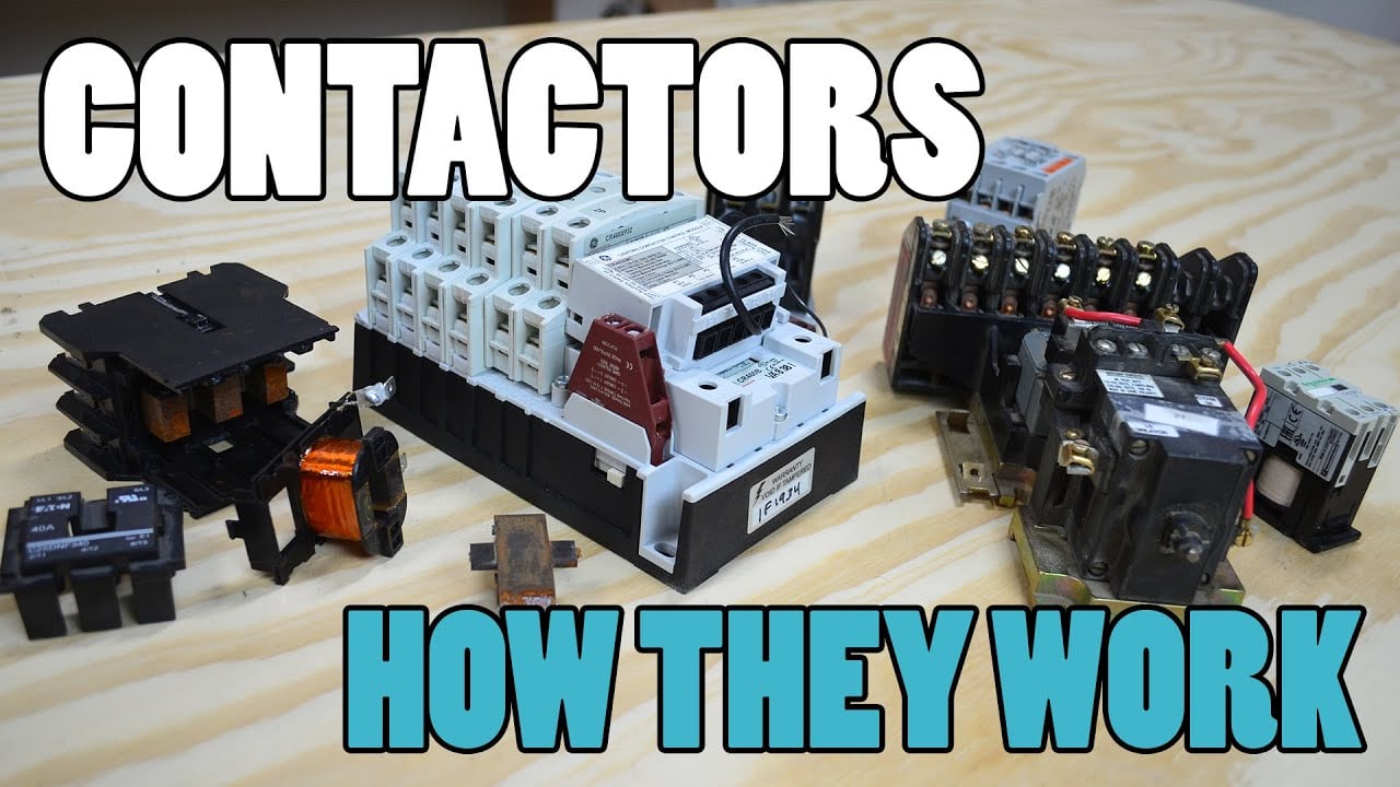
Watch the Electrician U educational introduction.
Frequently asked questions
Is every normally closed auxiliary contact a mirror contact?
No. Obtain documentation for the exact contactor and accessory arrangement that declares the required relationship.
Are mirror contacts and mechanically linked relay contacts identical terms?
No. Verify the device scope, applicable standard and manufacturer’s definition instead of treating the labels as interchangeable.
Does mirror feedback prove that equipment is safe to touch?
No. Follow the approved isolation and absence-of-voltage procedure, including other sources and stored energy.
Can a matching auxiliary block be substituted without review?
Not when the approved feedback arrangement depends on the specific combination. Review identity, mounting and supporting evidence first.
Product and related engineering references
Request the current documentation for the CZWH100A Sayoon product reference. Use the DC contactor selection guide for the full application. Related reviews: auxiliary-contact load rating, feedback plausibility, weld-detection methods.
Technical sources and scope
- IEC 60947-4-1 standard preview from VDE Verlag: apply the stated scope and exact equipment instructions; this does not certify the illustrated product.
- 29 CFR 1910.333 electrical work practices: use the applicable jurisdiction and approved isolation procedure.