A DC contactor for a resistive heater must match the heater’s actual DC voltage, cold and hot current, switching frequency, enclosure temperature, and protective arrangement. Calculating current from heater watts is a starting point, not a complete selection. The heater element may change resistance as it warms, while wiring and controls can introduce additional behavior. Separate the main-contact duty from the coil supply, and obtain a rating for the complete operating condition. This guide focuses on engineering review for DC-fed heater banks; it does not establish that any photographed contactor is approved for a particular heater or temperature-control system.
Define what the contactor actually switches
Start with the power schematic. A contactor directly feeding a heater element has a different duty from a contactor upstream of an electronic heater controller. In the second arrangement, the input can include capacitors and power electronics. Calling the equipment a heater does not make its input a simple resistor. Ask whether the contactor closes onto the element, an electronic converter, or several branches with separate controls.
Also establish its job. A main contactor might enable a heating cycle, disconnect the supply after an abnormal temperature, or provide a controlled stop while another device regulates power. These actions create different numbers of loaded operations. A device that carries current for hours and opens occasionally needs a different endurance review from one commanded every few seconds. Record normal commands and protective commands separately.
This page addresses the heater-specific combination of resistance, supply variation, thermal surroundings, and control cycling. The general utilization-category guide explains rating categories; it cannot supply missing heater measurements or authorize a particular DC operating point.
Calculate current at a stated operating point
For a steady DC resistive operating point, power equals voltage multiplied by current. When resistance is known at that same condition, current equals voltage divided by resistance. The OpenStax electrical-power reference below explains these relationships. Keep the conditions attached to the numbers: rated watts at one voltage and one element temperature cannot automatically describe a different supply or a cold start.
Consider a hypothetical element with a resistance of 12 ohms at a defined temperature. At 48 volts it draws 4 amperes and dissipates 192 watts under the ideal steady model. At 60 volts, if that resistance remained 12 ohms, it would draw 5 amperes and dissipate 300 watts. These are arithmetic examples, not contactor ratings, safe heater settings, or recommended system values. A real element’s temperature and resistance may change at the higher power.
For a battery-fed heater, collect the full specified battery operating range. Include charging conditions if heating can remain enabled during charging. The highest nominal system label may still omit transients or the operating maximum. Ask the heater supplier for the resistance and power information needed to evaluate the relevant conditions rather than inventing a current margin.
Compare cold and hot resistance
Many metallic heater elements have a positive temperature coefficient: their resistance rises as they warm. The effect depends on material, construction, and temperature range. Other technologies, including semiconductor heating elements, may behave differently. Use the actual heater’s information; a generic copper coefficient is not a substitute for a heater-alloy curve.
A room-temperature resistance reading can help identify an element, but it does not describe every startup or hot-restart condition. Record ambient temperature, measurement method, element configuration, and whether parallel branches were isolated for the measurement. Where leads contribute appreciably to the result, account for that contribution using an appropriate measurement method. Measurements must follow the approved deenergized procedure.
The selection record should distinguish cold-start current, stabilized current, and any current-limiting control behavior. If the supplier provides only rated hot power, request the missing startup information. Do not assume a universal heater inrush multiplier. A PTC assembly, metallic wire element, and heater controller can demand different evidence even when their labels show the same nominal watts.
Build the heater duty record
| Review item | Evidence to collect | Selection implication |
|---|---|---|
| Electrical operating point | Maximum operating DC voltage and element current | Match voltage and switching-duty documentation |
| Cold start | Heater-specific cold resistance or current evidence | Do not assume a universal inrush multiplier |
| Temperature regulation | Actual contact operations per cycle and service interval | Review endurance at the intended duty |
| Local temperature | Enclosure air and nearby heater conditions | Use the specified thermal operating envelope |
| Abnormal heating | Defined detection, interruption and reset response | Assess the complete protective function |
Use the table as a collection checklist, not as a rating conversion rule. Its electrical relationships are supported by the OpenStax references; the actual limits must come from the selected heater, contactor, protective devices, and system design. Resolve missing conditions before approving an ordering code.
Separate temperature regulation from contactor endurance
A thermostat or controller can request heat much more often than expected from the production schedule. The relevant count is the number of contact operations, including startup checks, temperature regulation, protective trips, resets, and commissioning. Estimate those operations over the intended service interval using the actual control logic and then compare them with documented endurance under matching load conditions.
For frequent power modulation, the design team may evaluate a suitable electronic switching stage while retaining a contactor for another defined function. That is a system architecture decision, not permission to replace one component blindly. Electronic devices have their own thermal, protection, leakage-current, and failure-mode requirements. Establish which device interrupts normal heater current and what happens if that device fails conducting.
Avoid rapid contactor cycling caused by a narrow control band or noisy temperature measurement. Fixing the controller settings without reviewing process stability can also create problems, so investigate the demand signal and measured temperature together. Capture the reason for each transition rather than treating a coil click as proof that the heating process is controlled correctly.
Review the enclosure as well as the element
The heater’s useful output becomes heat somewhere in the machine. A contactor mounted near a hot element, exhaust duct, or poorly ventilated enclosure can experience a temperature well above room conditions. Define the air temperature around the contactor during stabilized operation and after shutdown, when airflow may stop but surrounding parts remain hot.
Include heat generated in terminals and conductors. Their suitability depends on the approved connection method, conductor temperature rating, terminal arrangement, and installation instructions. Do not use a larger contactor as the sole remedy for a loose connection or an enclosure with inadequate cooling. The cause must be identified before changing components.
Keep temperature evidence tied to the complete assembly. An open-panel test may not represent a closed enclosure beside an operating heater. Likewise, a thermal image does not independently establish an internal contact condition. Use measurement methods and acceptance limits defined for the actual equipment, with qualified personnel responsible for energized work.
Plan abnormal heating and failed switching
Evaluate the case where heat remains enabled after the controller requests off. Possible causes include a welded power path, incorrect wiring, a controller output remaining active, or a false temperature reading. The system’s response must address the hazard identified by its risk assessment; an auxiliary contact alone does not prove the heater has lost electrical power.
An overtemperature function should have a clearly documented action, reset behavior, and relationship to the normal temperature controller. Where an independent protective function is required, the architecture must support that requirement. Do not assign a safety level or claim independence merely because two devices appear on the drawing.
Coordinate fault protection separately from temperature control. A contactor is not automatically a short-circuit protective device, and a fuse selected for a fault does not necessarily prevent dangerous process overheating at normal current. Review the protective device, prospective fault conditions, wiring, and contactor evidence as an assembly. Keep electrical protection and process-temperature protection distinguishable in the documentation.
Check the coil circuit and restart sequence
The main circuit might use one DC voltage while the operating coil uses another. Confirm the exact coil option, available control supply, polarity where applicable, suppression arrangement, and release behavior. A power-circuit calculation based on heater watts says nothing about whether the coil will pick up reliably through the installed harness.
Define restart after a trip or loss of control power. Automatic reenergization can restart heating before airflow, fluid circulation, or another necessary condition has returned. The control sequence should verify the conditions required by the actual heater system before enabling power. A manual reset may be appropriate for some hazards, but the final design follows the equipment’s requirements and assessment.
For diagnosis, log the heat request, coil voltage, contact feedback, heater current, and temperature state against the same time reference. These signals help separate a regulation issue from a switching issue. Do not repeatedly reset an unresolved overtemperature event simply to restore production.
Send a useful selection request
Give the supplier a concise duty sheet containing the maximum operating DC voltage, measured or documented cold and hot currents, heater type, branch arrangement, switching sequence, operation count, local ambient temperature, and protection scheme. Include the coil supply and installation constraints as separate fields. State which values are measured and which remain assumptions.
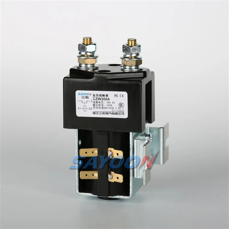
Request the exact ordering code, applicable DC rating conditions, endurance information for the proposed duty, connection instructions, and any limitations relevant to the installation. Product photographs are useful for checking external construction and space planning; they cannot confirm breaking performance, thermal suitability, or a protective function.
Before release, agree on an assembly validation plan with explicit operating conditions and acceptance criteria. The useful outcome is a traceable match between the heater duty and documented device evidence, followed by testing of the actual control sequence. Preserve those records for maintenance and replacement so that a later purchase does not silently change the approved coil, terminals, or duty assumptions.
Educational video
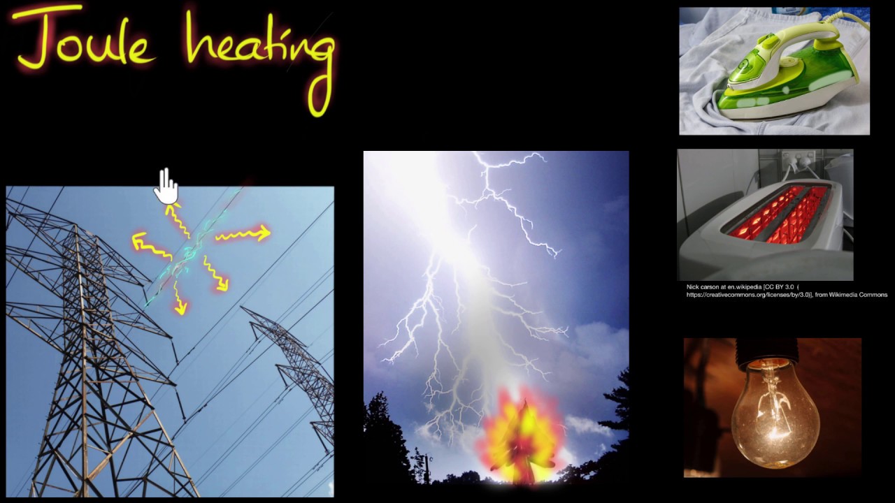
Khan Academy explains resistive heating and the relationship between current, resistance and heat. This supports the heater-power discussion; it does not qualify a switching device.
Frequently asked questions
Can I size the contactor from heater watts alone?
No. Watts and voltage help calculate a stated operating current, but selection also needs startup behavior, the actual DC switching duty, operation count, thermal conditions, and protective coordination. An electronic heater controller can make the input different from a simple resistor.
Does a resistive load mean there is no switching stress?
No. Current must still be made and interrupted at the relevant DC voltage. Temperature, wiring, contact cycling, and the complete load arrangement remain part of the review. Use documented DC performance rather than transferring an AC rating.
Is cold resistance the same as running resistance?
Not necessarily. Resistance depends on the heater material and temperature. Obtain the heater-specific relationship and identify the conditions associated with every measurement. Do not apply a universal inrush factor to all heater technologies.
Can a contactor replace overtemperature protection?
A contactor can be an actuator within a protective arrangement, but its presence alone does not create a complete overtemperature function. Detection, control logic, interruption capability, failure response, and restart behavior require a system-level assessment.
Product documentation and complementary guides
Use the CZW200A external-construction reference to discuss physical arrangement with Sayoon, and request current application-specific documentation before selecting it. Start with the DC contactor selection guide. Complementary subjects include Contactor Utilization Categories: How to Match the Load and Duty, Contactor Duty Cycle: Continuous, Intermittent, and Repetitive Service, How Ambient Temperature Changes DC Contactor Current Rating.
Primary references and scope
The physics references support the stated relationships for resistance, power and temperature. They do not provide device ratings or approve a heater installation.