مواصفات تحمل جهد لفائف المقبس هو الجهد المسموح به عند قواطع الملفات بالنسبة للظروف المحددة لخيارات المكونات والدوائر المتصلة بدقة. هذه ليست نسبة يمكن نسخها بنجاح من نموذج آخر، كما أنها لا تعني أيضًا معاملة الجهد الرئيسي للوصلات الدقيقة. التصميم الموثوق يحدد ما إذا كانت الدائرة القابلة للاتصال متوافرة أم لا. التقاط في أدنى جهد إمداد ملقن، يظل الجهاز مستقرًا أمام الاضطرابات العادية، ويمنع حدوث ضغط كهربائي أو حراري مفرط عند أعلى جهد إمداد. يبدأ الإجابة من رمز الترتيب المحدد وبيانات الشركة المصنعة؛ ثم يتم التحقق من ذلك في المقومة المثبتة، وليس من خلال عرض الطاقة غير الملقن.
ما تعنيه فئة الجهد وما لا تعنيه
الجهد الاسمى للدوائر هو وصف ترتيب مناسب، مثل خيار 24 فولت DC. يتراوح نطاق التشغيل ضمن النطاق المحدد من قبل الشركة المصنعة وفقًا لظروفها. ويتمثل التقاطع في الانتقال من الوضع المفتوح إلى الوضع المغلق تمامًا؛ والتقييد هو بقائه مغلقًا بعد التقاطع؛ والإنقطاع هو الانتقال إلى الوضع المفتوح مع انحطاط المجال. هذه الحدود ليست قابلة للاستبدال. وعلى وجه التحديد، قد لا يتمكن موصل قائم على اتصال من البقاء مغلقًا بعد حدوث حدث منخفضة الجهد من إعادة إغلاقه عند نفس الجهد. ويؤكد نجاح واحد ظاهري على منصة الاختبار على عدم كفايته في ضمان الحد الأقصى للتقاطع أو القدرة على التحمل في الظروف القاسية.
قد يتضمن دائرة الملف أيضًا مكيفًا اقتصاديًا، أو ديود، أو مخلّص، أو مشغل إلكتروني. وتغيّر هذه المكونات التيار والشرط المتعلق بالقطبية والسلوك الديناميكي. الدائرة الرئيسية لا يستخدم بالضرورة ملفًا عالي الجهد: تستجيب التصنيفات المذكورة أدناه لمسائل هندسية مختلفة. احصل على مواصفات الجهد الدقيق للقطعة المحددة، بما في ذلك خيار الملف، والدرجة الحرارية المحيطة، ومعدات التحكم. لا تعتبر صور المنتجات بمثابة موافقة كهربائية؛ إذ قد يكون لدى المنتجات التي تبدو متشابهة ملفات مختلفة.
توضح الحدود المحددة في المنشورات الأسباب وراء أهمية النموذج. تقدم شركة Schneider Electric شرائح TeSys Giga بتصنيفات محددة حسب الطراز, ، بما في ذلك 0.8–1.1 ضعف الجهد التحكمي المقدر لبعض الإصدارات ذات النطاق العريض. قوس شيندربير 24 فولت DC مختلف يحدد حدود تشغيله الخاصة. لا يشكل أي من هذين الرقمين تصنيفًا لشركة Sayoon. إنما يوضحان أن المهندس يجب أن يستخدم منتج مختار اعلن عن نطاق محدد بدلاً من وضع شعار شامل لجميع الصناعات. حيث إن وثائق Sayoon لا تحدد حدًا، فاحصل على أدلة محددة لنوع النموذج ولا تبتكرها.
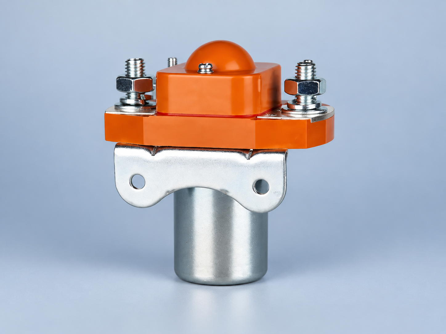
إنشاء ميزانية الجهد الفعلي في الملف
يكون نقطة القياس الصحيحة A1–A2 أو زوج المقايضات المحدد على الجهاز المثبت، أثناء دوران التيار. قد يكون الإمداد صحيحًا بشكل رسمي، ولكن المقاومة في المقاومة أقل بسبب انحراف مصدر التيار، وانخفاض جهد خرج التحكم، ومقاومة اتصال الموصل، ومقاومة الكابل، أو العودة المشتركة. وعلى العكس، قد تعرض حالة الشحن العالية أو الإمداد الموجه المقاومة إلى المزيد من الجهد من المتوقع. استخدم بنية التوصيل الفعلية في كلا الاتجاهين: من المورد إلى المقاومة ومن المقاومة إلى المورد. وشمل أي حماية متصلة أو فقدان في حالة التشغيل.
للحصول على ميزانية أولية، اكتب Vسلك = Vالمصدر، المعبأ − Vالسائق − أناسلكRحلقة − Vالروابط. هذه معادلة محاسبية هندسية، وليست بديلاً لقياسات القياس. لا يكون تيار الملف دائمًا متساوياً عند الاستخدام، أو عند الاحتفاظ به، أو عند بدء التشغيل البارد، أو عند الاستخدام في وضع الاستقرار الحراري. بالنسبة لدائرة قياسية تبلغ قيمتها 24 فولت، فإن مصدرًا مدفوعًا بـ 22.8 فولت، وفقدانًا في العاكس يبلغ 0.4 فولت، وفقدانًا في الأسلاك/الموصلات يبلغ 0.7 فولت، سيؤدي إلى الحصول على 21.7 فولت في الملف. هذه الأرقام هي مجرد مثال رياضي تم تصميمه فقط: فهي ليس المستويات المقبولة لأي من طرازات Sayoon. قارن الحد الأدنى المقدر بالحد الأقصى المكتوب في الوثائق الخاصة بالنموذج الفعلي، ثم تحقق من ذلك باستخدام اختبار مجهز بالمواد.
في الزاوية العليا، قم بإعادة التمرين باستخدام أعلى مصدر موثوق به لجهد التيار الكهربائي وأقل فقدان في الأسلاك. يجب تقييم المقومة المتولدة بشكل دائم عند أعلى درجة حرارة وبيئة وأداء مناسبين، وليس فقط لعملية إغلاق واحدة. إذا كانت هناك حدوثات عابرة في امدادات الطاقة، استخدم معدات تسجيل مناسبة لتفريق الحدوثات القصيرة عن حدوثات الجهد الكهربائي المرتفع المستمر. فيما يتعلق بالمسألة الفردية الخاصة بتصميم جهاز الإخراج، راجعنا دليل لفائف التحكم PLC و دليل استهلاك الطاقة في المقبس.
| الحالة التشغيلية | الجهد المطلوب التقاطه في المقومة | أدوات التحقق من السلوك | الأدلة والقرار |
|---|---|---|---|
| البدء البارد، إمداد منخفض | الجهد الأدنى الذي يتم تحميله في A1–A2 أثناء الاستلام | إغلاق كامل دون وجود أي ضوضاء في الظروف المحددة | قارن مع نطاق الاستلام الدقيق وقم بتسجيل السلسلة الحالية |
| العملية العادية | توازن جهد الملف مع تشغيل الحملات الأخرى للتحكم | التحكم المستقر والردود المتوقعة | خسائر الوثائق والقيود والأجهزة الخاصة بالقيادة |
| الاضطراب وإعادة التشغيل | Lowest voltage and duration during source sag | Expected drop/reclose sequence, no repeated partial closure | Record system-safe response, not just a single pass |
| High supply, hot ambient | Maximum sustained terminal voltage | Temperature and hold current within the exact rating | Obtain coil-duty and ambient limits for ordered model |
| Turn-off | Transient voltage and decay after driver opens | Required release timing with suppression installed | Check driver, suppressor and contactor together |
Pickup, hold and dropout require separate checks
The magnetic force during pickup must move the armature across its full travel against spring force. Once closed, a different current may be enough to hold it. Consequently, observing a closed contactor at reduced voltage does not show that it would reliably التقاط there. Some electronic coils intentionally reduce current after closure; others are designed for particular pickup and hold waveforms. Use the exact technical document to distinguish those behaviors. If the part has a wide-band electronic coil, confirm its input band, input polarity and recovery response rather than assuming it behaves like a simple resistive winding.
Undervoltage is more serious than a missed command. Schneider Electric describes the risks of low contactor control voltage, including slow closing, unstable holding and contact wear. Those risks are useful general engineering warnings, but the exact thermal mechanism and thresholds depend on coil construction. Do not infer that every Sayoon DC coil will have the same AC-style inrush profile. Instead, measure pickup current and contact motion for the model in question, then ensure the system prevents repeated chattering under supply faults.
Dropout is a different limit again. A suppressor intended to protect the controller can prolong the decay of coil current. If rapid isolation is required, confirm the release time using the installed suppression network at voltage and temperature extremes. Our flyback and release-time discussion covers that interaction; it should not be used to override the product’s wiring instructions. A feedback contact can detect command/position disagreement, but it does not independently prove that the high-energy path has been isolated.
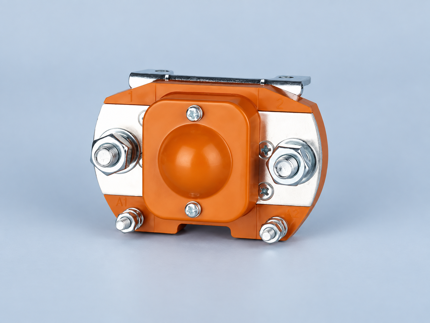
Measure the corners safely and repeatably
First identify all energy sources, stored-charge paths and the approved isolation method for the machine. Work on the control circuit under site procedures with correctly rated instruments and qualified personnel. The control output being off is not by itself proof that the main DC circuit is safe. Record the exact contactor order code, coil option, driver and suppressor, harness route, power-supply model, ambient temperature and document revision. Keep the control and main-circuit ratings in separate columns of the test sheet.
Measure the unloaded source only as a diagnostic starting point. Then monitor voltage directly at the coil during the actual closing event with the other credible control loads operating. A multimeter may miss a brief sag; use an appropriately isolated recorder or oscilloscope if the problem occurs during milliseconds of pickup. Measure hold voltage after the thermal state has stabilized, and repeat near the minimum and maximum intended supply conditions. Do not arbitrarily lower or raise a live installation’s source beyond approved limits to “find the edge.” A controlled engineering test should define its safe boundaries beforehand.
If a unit closes at room temperature but fails in the field, compare traces at the same coil terminals during cold start, hot enclosure conditions and simultaneous control loading. Check connection resistance, a shared return, PLC output drop and source current limiting. Record whether the coil receives the command, whether the armature fully seats and whether the auxiliary feedback changes. A power-circuit load problem should be diagnosed separately from a coil-voltage problem. For long harnesses, our control-cable voltage-loss guide gives a more detailed loop calculation.
What to request before selecting a replacement
Supply the vendor with the exact supply envelope at the coil, not only “24 V DC.” Include measured minimum during pickup, maximum sustained voltage, output topology, cable length and conductor size, ambient range, switching rate, suppression, coil energization duration and any economizer. Ask for the corresponding coil operating range, pickup and release characteristics, continuous-duty status, connection drawing and limits over temperature. If a replacement uses a different coil or built-in electronics, repeat the control-circuit compatibility review even if the main current rating is identical.
ال Sayoon SZJ200A-D product page identifies one real construction for this discussion. The picture is illustrative, while approval requires the actual drawing and option documentation for the item ordered. For application-level selection, start from our دليل اختيار موصل التيار المستمر and send the complete coil-voltage budget with the RFQ. A different coil option or driver can be a better fit than asking a standard option to operate outside its specified limits.
Video: checking a contactor coil
This independent demonstration shows the basic measurement distinction between the coil and power contacts. It is educational, not a Sayoon-specific voltage tolerance or permission to test an energized high-voltage system.
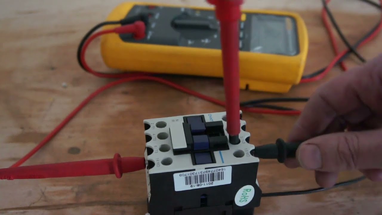
Watch the independent coil and contact demonstration on YouTube.
الأسئلة الشائعة
هل من الممكن أن تعمل المقومة 24 فولت عند كل جهد قريب من 24 فولت؟
لا. تنتمي النطاق التشغيلي المسموح به إلى الطراز والنوع المحدد من الملفات وفقًا لظروف الحرارة والعمل المحددة. قم بقياس الجهد عند الحمل على الملف، ثم قارن الرقم بذلك الوثيقة.
هل يمكن أن يظل مفتاح الاتصال مغلقًا عند الجهد المنخفض أن يظل مغلقًا أيضًا عند الاستراحة؟
ليس بالضرورة. فإن حالة "التقاط والحمل" هي حالات مختلفة؛ إذ لا يمكن لعملية اختبار "التقاط والحمل" أن تثبت الحد الأدنى من الجهد المقبول للتقاط.
هل يحدد تصنيف الجهد الكهربائي الرئيسي جهد المقبس؟
لا. الاتصالات الرئيسية ومجرفة التحكم عبارة عن دوائر منفصلة. احصل على كل من التصنيفين من معلومات الطلب والرسومات الخاصة بالمنتج المحدد.
أين ينبغي قياس تحمل الجهد؟
في محطات المقاومة المثبتة أثناء الاستلام والاحتفاظ، مع أحمال تحكم تمثيلية والكابل ومحول الطاقة الفعليين في الدائرة. لا يكفي قياس إمداد غير مجهّز.





