A 120V DC contactor should be specified by separating its main-circuit rating from its coil supply. “120V” in a catalog often describes a control coil, while the main contacts may be rated for a different circuit voltage. It can also describe the nominal bus the buyer wants to switch. Resolve that ambiguity before comparing current, mounting or price. Confirm DC carrying, making and breaking duty for the actual load, then choose the exact coil variant and control arrangement. A 120V AC coil and a 120V DC coil are not interchangeable.
This guide helps OEM purchasing and engineering teams define the correct specification. It addresses selection and replacement evidence, rather than giving a universal wiring diagram or assuming that every product with “120V” in its listing serves the same application.
Identify whether 120V refers to the load or the coil
Draw the main power path and the coil control path separately. Mark the voltage range at each, including startup, shutdown and supply variation. A product listing can combine a high-current main-contact rating with a 120VDC coil option in one headline. Reading the headline as a 120VDC load rating can therefore lead to an unsuitable comparison.
If the requirement is a 120V nominal main bus, obtain its actual maximum voltage and load conditions. If the requirement is a 120VDC control supply, obtain the coil’s permitted range, duty and operating demand. A design can meet one requirement and fail the other. Include both in the RFQ even when they happen to have the same nominal value.
Also resolve the meaning of “DC contactor.” Some listings use the phrase for the load circuit; other descriptions emphasize the coil. Require explicit main-circuit DC ratings and explicit coil characteristics. The complete ordering code is more reliable than a family name or an online store filter.
Confirm AC versus DC coil variants
A coil operates the electromagnetic mechanism, but its construction and associated electronics can depend on the intended supply. Use the manufacturer’s stated AC or DC supply type, frequency where applicable and voltage range. Do not substitute an AC coil for a DC coil on the basis that both labels contain 120V.
The control arrangement can include an economizer, internal suppression, polarity-sensitive electronics or a separate driver. Ask for the exact variant’s wiring description, pickup demand, holding demand and release behavior. A family data sheet that lists several options does not establish which option is installed in a replacement part.
Check the supplier quotation against the approved ordering code before purchasing. Then check the delivered label and drawing before installation. This is especially important for spare parts ordered from multiple distributors: similar housings and a shared base model do not make the coil options identical.
Use separate acceptance fields
| Specification field | Required information | Common purchasing mistake |
|---|---|---|
| Main-circuit voltage | Actual DC operating range and connected sources | Using the coil voltage as the main-contact rating |
| توريد الملفات | AC or DC, nominal voltage, permitted range and exact option | Accepting a 120V label without the supply type |
| Carry duty | Current profile, conductors, mounting and temperature conditions | Treating a catalog current as an installed thermal guarantee |
| Switching duty | Closing inrush and opening conditions with current direction | Assuming the carrying current is also the breaking current |
| Control interface | Driver demand, suppression, polarity and release requirements | Adding coil suppression without checking the internal circuit |
| Replacement envelope | Terminal arrangement, clearances, mounting and feedback | Matching overall size while changing the operating sequence |
The table is a specification checklist rather than a list of rated values. Each accepted entry should point to an approved drawing, supplier statement or suitable validation result for the exact variant.
Check voltage at the coil during pickup
A control supply can read correctly at its output while delivering less voltage at the coil under pickup demand. Include the cable path, connectors and driver in the review. Obtain the manufacturer’s operating range and determine whether the supply remains within it during the conditions the equipment will actually encounter.
For a remotely mounted contactor, conductor drop and output-device drop can be relevant even when the main load cable is adequate. Review the coil circuit on its own terms. A contactor that chatters or fails to pull in fully should not be accepted because it worked once with short bench leads.
Consider control supply recovery as well as steady operation. Decide whether the controller should automatically reclose after a dip, wait for a reset or enter a defined safe state. Record that behavior in the equipment sequence and verify it. A coil specification alone cannot decide the machine’s restart policy.
Choose the main contacts for the actual DC duty
If the main bus is nominally 120VDC, document the source’s full operating range. A battery, regulated converter, charger or industrial DC supply can have different limits and abnormal conditions. Do not assume that the nominal value is the maximum voltage at the contactor terminals.
Define normal carrying current, closing current and opening current separately. Closing into a motor, capacitor bank or resistive load presents different conditions. Opening an inductive circuit requires appropriate DC interruption evidence. AC switching ratings cannot be transferred to a DC load merely by choosing a numerically higher voltage rating.
ال IEC 60947-4-1 official overview identifies its contactor and motor-starter scope. Check the applicable classification and exact product evidence. The presence of a standards reference in a brochure does not establish every requested duty or certify the complete equipment assembly.
Review direction, protection and stored energy
Trace every source that can feed the contactor’s main path. Include regeneration, parallel supplies, chargers and stored capacitor energy where applicable. Some contactors have a documented preferred current direction because of their arc-control arrangement. Verify both terminal assignment and the duties permitted in any reverse-current condition.
A load-opening command and a short-circuit event are separate duties. Identify the protective device expected to clear a fault and obtain the relevant coordination evidence. A contactor should not be treated as a general-purpose fault interrupter because it has a large continuous current rating.
Opening also does not prove that a downstream circuit is safe to touch. Residual energy or another source may remain. The disconnect boundary, discharge arrangement and maintenance isolation method should be explicit in the drawing. Review these before accepting a replacement that changes the number or location of main poles.
Account for terminals, mounting and heat
Compare the terminal arrangement and connection method, not only the case dimensions. Conductor bending space, lug geometry, torque instructions and clearance to adjacent live parts can determine whether a replacement fits the assembly. A new part that requires improvised terminal hardware deserves another design review.
For an open-frame contactor, the equipment enclosure is particularly important. It determines accessibility, contamination exposure and nearby clearances. The product’s external appearance is not evidence that an installation is protected against dust, moisture or accidental contact. Request the manufacturer’s mounting and environmental guidance.
Thermal validation should represent the installed current profile, enclosure, conductors and neighboring heat sources. Review hot-terminal behavior and the coil’s own heating over the assigned operating time. Matching a nominal current number does not compensate for a changed conductor layout or insufficient cooling.
Validate a replacement against the approved sequence
Begin with the original specification, actual duty and reason for replacement. Record the original part’s complete code and any control electronics, auxiliary contacts or interlocks used by the machine. If the original documentation is incomplete, reconstruct the requirement from approved equipment information rather than copying a distributor description.
Compare pickup, holding and release behavior; control supply variation; feedback timing; mounting; and the assigned switching events. A replacement with different suppression can release differently. A different auxiliary arrangement can alter the controller’s state check. A part that fits and clicks can still be functionally unsuitable.
For covered workplace electrical servicing, 29 CFR 1910.333 addresses de-energization, lockout and verification. Complete the applicable safe-work process before inspection; a remote opening command does not establish an electrically safe condition.
Prepare an RFQ that avoids a wrong coil order
State whether the requirement is a 120VDC main circuit, a 120VDC coil, or both. Give the voltage ranges, load profile, making and breaking conditions, protection, control-output capability, environment and mounting information. Ask for a supported ordering code and require unresolved items to be identified before acceptance.
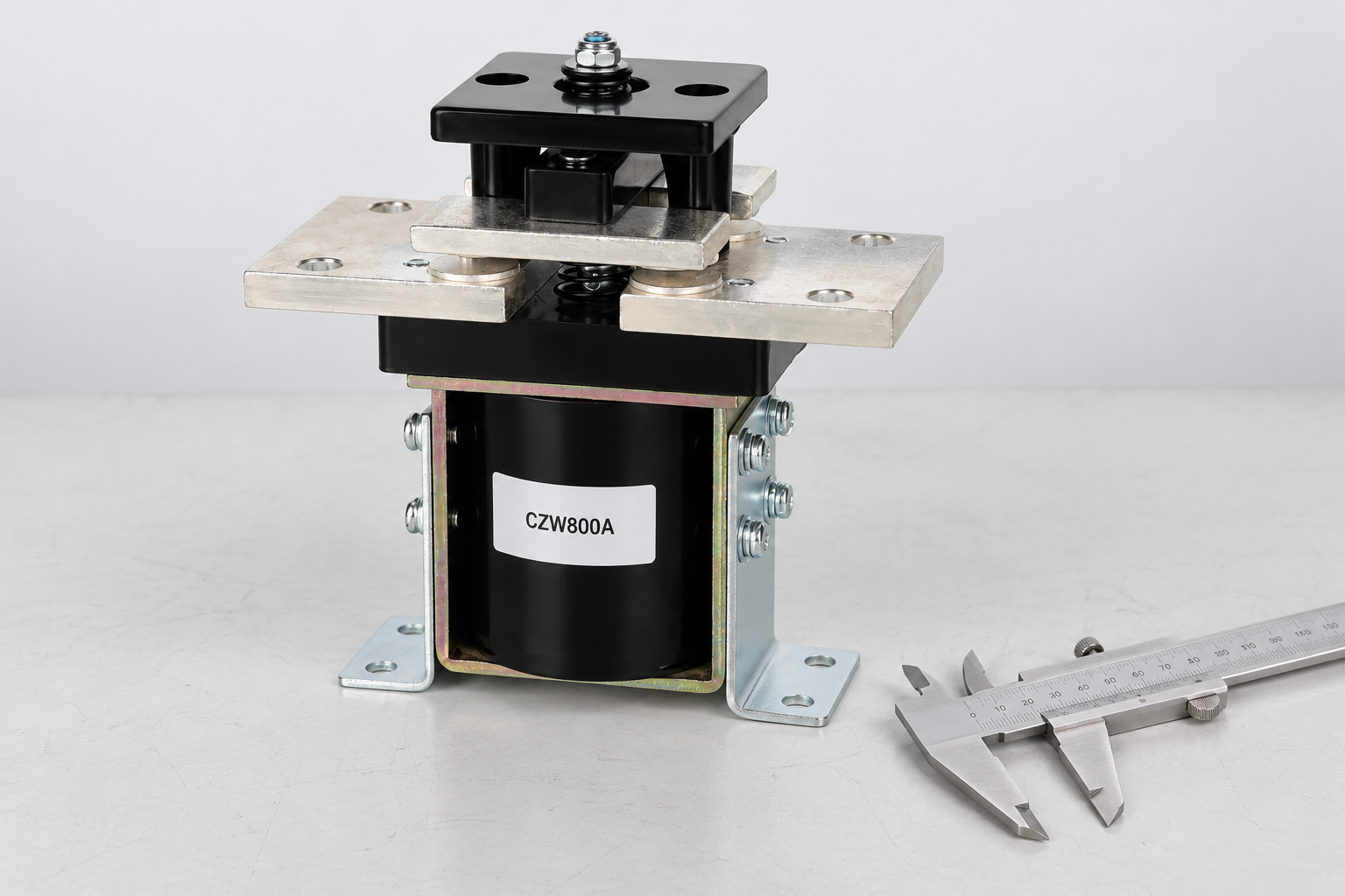
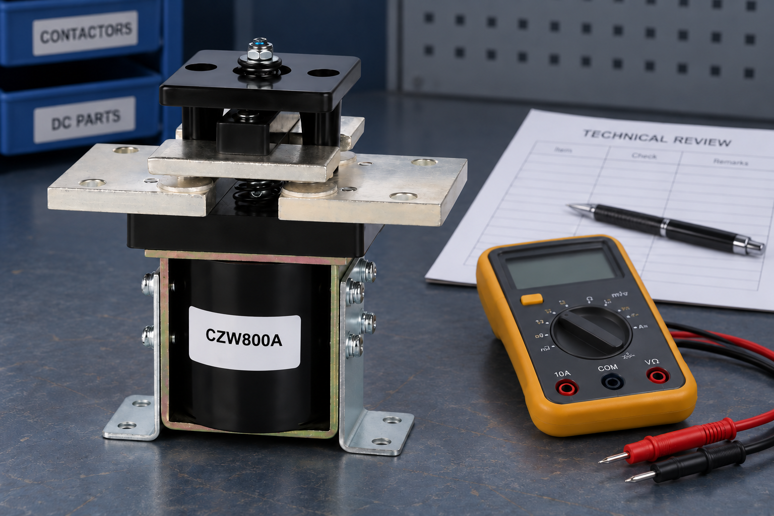
ال CZW800A product page provides the construction example illustrated here. Confirm the exact available coil variant and application ratings directly; the displayed product is not promised as a 120V coil version. Use the OEM specification checklist to record the evidence.
For complementary checks, review coil supply tolerance و mechanical versus electrical life. These topics address control stability and repeated duty without replacing the main-circuit assessment. The DOE electric-vehicle maintenance overview provides application safety context for battery equipment, not a product rating.
Keep the approved data sheet, drawing revision, supplier response and validation results together with the purchasing record. That makes a later reorder traceable and helps prevent an unreviewed coil or construction option from being substituted under the same short model name.
Watch the basic contactor principle
The Electrician U video explains the electromagnetic operating mechanism. It is educational background, not a 120VDC wiring instruction or qualification for the pictured product.

الأسئلة الشائعة
Does “120V DC contactor” always describe the main bus voltage?
No. A listing may use 120VDC for the coil supply. Confirm the main-contact DC ratings and the coil specification as separate fields for the exact ordering code.
Can a 120V AC coil replace a 120V DC coil?
Do not make that substitution without explicit manufacturer approval and design validation. The supply type, operating demand and associated coil electronics can differ.
What evidence is needed for a 120VDC main circuit?
Provide the full operating voltage range, current profile, closing and opening conditions, direction, protection and installation. Require documented DC duty capability for the selected variant.
Is matching current and mounting size enough for replacement?
No. Check coil type, supply range, terminal arrangement, switching duty, suppression, feedback and operating sequence. Retain the approved ordering code and supporting evidence.





