Contactor hot switching means making or breaking a circuit while electrical energy is present at the contacts. Cold switching means arranging the sequence so the contacts change state without the relevant load energy being applied. These terms describe electrical duty, not whether the enclosure feels warm. A contactor that normally moves without load still needs a justified response to a failed converter, residual charge or an emergency opening.
For DC battery and industrial systems, the useful question is not simply whether the normal current command is zero. It is whether the voltage, current, stored energy and timing at the actual contacts meet the documented conditions for that switching event.
Carrying and switching are different ratings
A closed contact can carry current without repeatedly creating and extinguishing an arc. Opening a live circuit introduces a changing gap and potentially an arc, while closing can introduce bounce and inrush. These are different stresses even when the same current number appears in the operating description.
NI’s switching guidance distinguishes switching current from carrying current and identifies hot switching as a contact-life consideration. Those instrument-relay explanations establish the distinction; they do not provide an application rating for a high-current contactor. Obtain the actual DC making and breaking data for the product and load.
A claim that a device can carry a particular current therefore does not mean it can interrupt that current at every voltage. Contact life also cannot be inferred from a mechanical endurance figure that omits the relevant electrical duty. Keep these quantities separate in the specification and supplier comparison.
Define the switching boundary
Identify the exact pair of terminals and current path being reviewed. A converter may report zero commanded output while its input capacitors remain charged. A motor may continue generating after the controller stops applying torque. A second source can maintain voltage on the far side of the contactor.
Distinguish current through a closed path from voltage across an open path. An open contactor can show negligible current yet have a substantial voltage difference across its terminals. Closing across that difference can create a charging event, so a zero-current reading taken before closure is insufficient evidence of a cold make.
Likewise, a disabled load command does not prove zero current immediately before opening. Internal control delays, measurement filtering and energy circulation can separate the requested state from the physical state. Use a defined measurement and acceptance criterion for the actual event.
A normal low-stress sequence
An engineered shutdown may first command the power converter to reduce current, verify the required electrical condition and then open the contactor. An engineered startup may establish an acceptable voltage relationship through a precharge path before closing the main device. The precise order and criteria belong to the equipment design.
This sequence can reduce routine switching stress when it is correctly implemented and validated. It does not automatically eliminate every switching event or change the device’s physical rating. Record the permitted current, differential voltage, stability time and maximum wait time using manufacturer and system requirements.
If the expected condition is not achieved, define an explicit response. Waiting indefinitely for a zero-current indication can leave a hazardous state energized. Opening immediately may require a different interruption capability. The system must resolve that tradeoff through its approved fault and shutdown strategy.
Classify each event separately
| Condition | Evidence to collect | Decision |
|---|---|---|
| Normal opening | Current at actual separation | Verify the intended unloaded condition |
| Normal closing | Voltage difference and current transient | Confirm acceptable making event |
| Precharge failure | Actual voltage and abort response | Do not close on timer alone |
| Converter cannot unload | Current and protective sequence | Check abnormal breaking capability |
| Control power loss | Actual release and circuit energy | Verify the supported shutdown response |
The table separates intended operation from abnormal operation. An installation may perform thousands of routine low-energy changes and a small number of more severe interruptions. Both duties matter. They should not be compressed into one average current or described collectively as cold switching.
This classification also helps service teams interpret event counters. A total operation count does not reveal how many cycles occurred under load. Where electrical life is a design concern, record relevant event conditions and fault history rather than assuming all operations consumed the same life.
Stored energy defeats simple labels
Capacitors can preserve a voltage after a supply is disabled. Inductors and rotating machines can maintain current or generate a voltage during a transition. The contactor is part of the energy path; it does not make the energy disappear because the controller has issued an off command.
Review precharge and discharge circuits, connected chargers, DC converters and auxiliary supplies. Include service equipment and external connections that can introduce an unexpected source. A diagram showing only the battery and main load may omit the path that determines the actual contact duty.
Do not classify an operation as cold solely because a normal controller value rounds to zero. Identify sensor resolution, offset, bandwidth and the location being measured. A value suitable for energy reporting may be unsuitable for deciding whether a short switching transient is within an accepted envelope.
Prove the timing relationship
Correlate the current waveform, voltage across the contactor, coil drive and relevant feedback on a common timeline. The purpose is to show the physical condition when contacts actually change state, rather than when software requests movement. Allow for delays in acquisition and communication.
A controller log sampled slowly may show current falling before an open command while missing a brief recovery pulse. Conversely, an auxiliary indication can lag or lead the main-contact transition depending on documented construction. Use signals for the conclusions they can support, without assigning an unverified mechanical relationship.
Instrumentation must match the circuit potential, available energy and measurement category. Qualified personnel should plan probes, isolation and protective arrangements before energized work. A normal bench oscilloscope connection is not automatically suitable for a floating high-voltage battery circuit.
Fault duty still needs a rating
Consider a converter that cannot stop drawing current, a precharge path that fails, a sensor stuck at zero and control-power loss. Determine what the contactor is required to do in each condition and what other protective devices are expected to clear the circuit. Avoid relying on a software sequence that the same fault can disable.
If a fuse or circuit breaker provides protection, coordinate its behavior with the contactor’s documented capability. The existence of a fuse does not itself establish safe interruption or short-circuit withstand. Use the applicable coordination evidence and the actual prospective fault conditions.
An emergency stop also needs a system-level definition. Removing coil power may cause opening while current remains, but the permitted stop response depends on the machine and risk assessment. This guide does not replace the required safety design or prescribe a universal emergency sequence.
Common specification mistakes
One mistake is requesting only continuous current because normal opening is intended to occur unloaded. This leaves an unanswered question about failed unloading. Another is specifying a breaking current without its DC voltage, load characteristics or permitted operation count. A single number cannot describe the whole switching envelope.
A third mistake is describing cold switching as a guaranteed life multiplier. Reduced electrical stress can be beneficial, but actual life depends on the component, environment and complete duty. Ask the supplier for evidence matching the intended conditions instead of applying a factor from an instrument relay or another product family.
Also avoid confusing a warm coil with hot switching. Coil temperature affects control behavior and thermal assessment, but it is a separate issue from energy at the main contacts during movement. Record both where relevant so diagnostic terms remain unambiguous.
Validation and purchasing checklist
Give the supplier a sequence description for startup, normal shutdown and abnormal interruption. Include maximum DC voltage, current direction, load type, capacitive energy and inductive characteristics where relevant. State which events are intended to be unloaded and how the design establishes that condition.
Request the applicable making, breaking, carrying and endurance information. Ask what measurement or application evidence is needed when a routine low-stress sequence is part of the proposal. Do not present a product illustration as proof that the device supports the intended duty.
For acceptance, keep the wiring and software revision, thresholds, timing logic and representative measured traces together. Include the behavior when verification fails, not just the successful sequence. A reproducible test record lets later changes be assessed without reconstructing the original engineering assumptions.
When a firmware update changes converter shutdown timing, revisit the switching evidence. The contactor part number may remain unchanged while its duty becomes more severe. The same applies to a larger DC-link capacitance, a new discharge path or a revised coil-suppression arrangement.
Educational background: coil and main contact paths
The Electrician U introduction explains the distinction between the operating coil and main contacts. Use it as background for identifying the switching device; it does not teach or approve the specific circuit reviewed above.
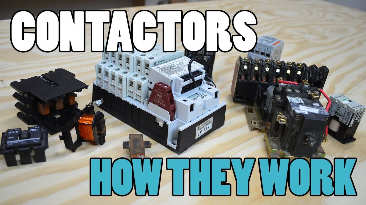
Watch the Electrician U introduction.
Frequently asked questions
Does cold switching mean the contactor is physically cold?
No. It describes electrical conditions during contact movement. Coil and enclosure temperature are separate thermal considerations and do not establish whether the main contacts switch a live load.
Is a zero-current command enough to prove cold opening?
No. Verify actual current and the physical transition with suitable timing evidence. Commands, reported values and contact movement can occur at different times.
Can a cold-switching design use only the carrying rating?
Not without resolving abnormal duty. Failed unloading, stored energy and emergency behavior can require interruption. Specify and validate the full set of required events.
Does precharge make every closure cold?
No. Precharge can reduce voltage difference and inrush when it works as intended. Its completion criteria, faults and the actual condition at main-contact closure still require verification.
Product documentation and related guides
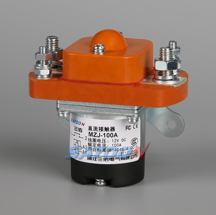
Send the actual schematic and duty to request current drawings and application evidence for the MZJ-100A Normally Open DC Contactor construction reference. Start with the DC contactor selection guide for the overall specification. Complementary reading: Contactor Making Current vs Breaking Current: Why Both Ratings Matter, Mechanical Life vs Electrical Life of a Contactor, DC Contactor Precharge Resistor Sizing: Inputs, Equations, and Checks.
Sources and measurement scope
Keep instrument identification, uncertainty and calibration evidence with the test record; NIST describes the basis of metrological traceability. The sources below explain the stated physical principles or measurement practice. They do not certify the illustrated contactor or prescribe a complete machine safety design.