Engineers should read a dc contactor symbol as a coil identity plus the contacts that coil operates, drawn in a defined rest state—not as a one-line wiring recipe. This article shows how coil shapes differ by drawing convention, how NO and NC rest states work, how main and auxiliary contacts diverge on the page, and how to verify a drawing before matching a SAYOON contact form.
What Does a DC Contactor Symbol Actually Represent?
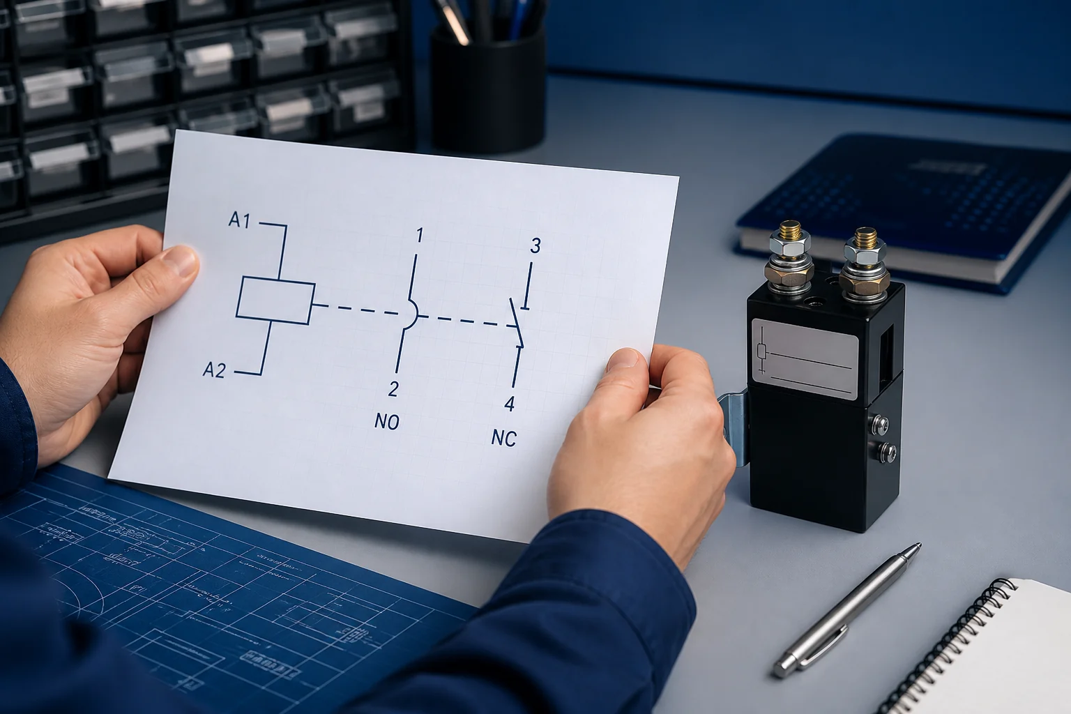
A DC contactor symbol encodes one coil and the contacts that coil moves, even when those parts sit on different sheets.
In plain terms, the coil is the control “magnet,” and the contact graphics are the switches it opens or closes. Educational schematic lessons describe that three-part anatomy clearly: coil, main contacts, and auxiliary contacts that may be drawn away from the coil body.
The reference designation belongs on the coil. Contacts elsewhere inherit that same tag so you can reconnect the story across rungs or pages. A dashed line sometimes hints that contacts are mechanically tied to the coil, but the tag—not page proximity—is the reliable link.
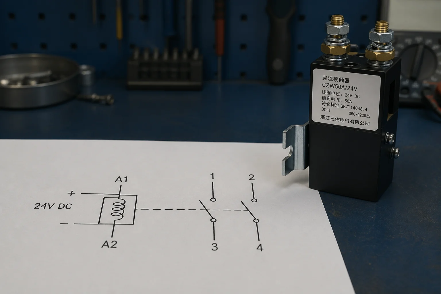
When an OEM reviews a DC forklift or UPS panel drawing, the first job is to locate every instance of that tag before debating wire colors or terminal screws.
| Symbol element | What it tells you | What it does not tell you |
|---|---|---|
| Coil graphic + tag | Which device is energized | Load current rating |
| Contact graphic | Switching state at rest / operated | Cable size or fuse size |
| Terminal marks (when shown) | Likely connection points | Proof that the installed model matches |
How Do Coil Symbols Differ on IEC and ANSI-Style Drawings?
Coil shape follows the drawing convention: many IEC-style sheets use a rectangle, while many North American control drawings use a labelled circle.
That difference is a language choice, not a different product physics. Cross-standard references still show contactor coils as recognizable actuator symbols with device or terminal notes nearby. IEC 60617 style libraries and ANSI/IEEE style libraries can both describe the same contactor function with different outlines.
A second literacy point matters for DC panels: some North American protection-oriented drawings use device function numbers, where AC switching devices and DC switching devices may carry different numbers in that numbering system. Treat those numbers as drawing vocabulary, not as a SAYOON catalog code.
If a supplier drawing looks “wrong” because the coil is a circle instead of a rectangle, check the title block and legend before rewriting the bill of materials. Mixed export projects often arrive with both conventions in one package.
The secondary reading cue is the contactor coil symbol annotation: coil voltage notes, A1/A2 marks, or a short description under the tag. Those notes bind the control source to the actuator the contacts follow.
How Should You Read NO and NC Contact Symbols?
NO means open in the drawing’s defined rest state; NC means closed in that same rest state—usually with the coil de-energized.
Professionally, “normally” refers to the unactuated mechanical condition on the legend, not to whatever the machine does most of the day. In plain language: a normally open contact waits open until the coil pulls in; a normally closed contact waits closed until the coil pulls in.
Common IEC-style auxiliary numbering often shows NO pairs such as 13/14 and NC pairs such as 21/22, but the graphic rest state still comes first. Confirm numbers on the device diagram for the model in hand.
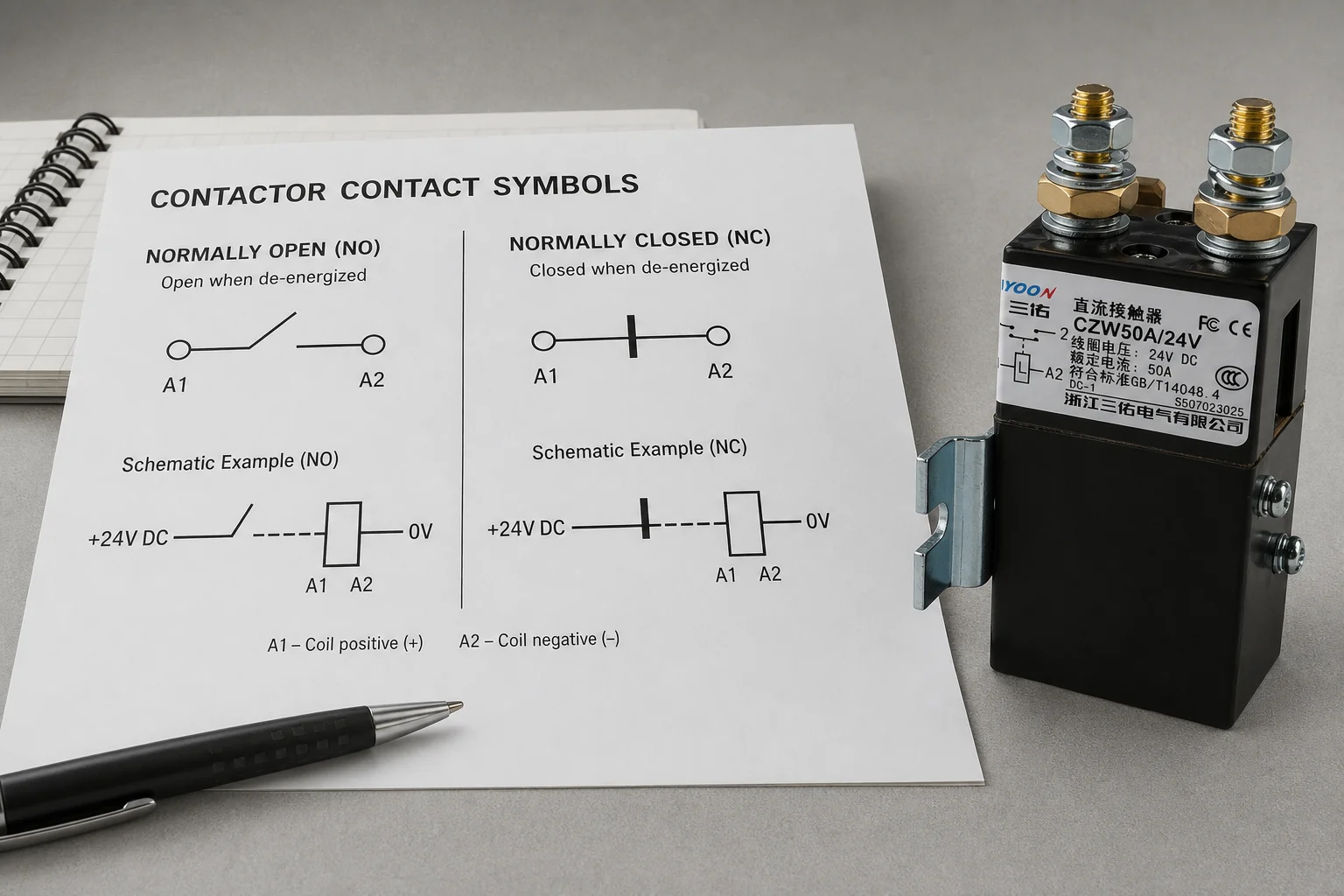
Procurement mistakes start when a buyer hears “normally closed” and assumes the load should be powered whenever the plant is running. On a battery disconnect sketch, that misread can reverse the intended fail behavior before anyone opens a datasheet.
Tip: If the drawing marks mechanically linked contacts, look for the special double-line / filled-circle cue used with mechanically linked contact elements. That mark is a documentation claim about contact coordination—not a generic decoration on every contactor symbol. Source: GT Engineering discussion of mechanically linked contact marking under the IEC contactor auxiliary standard annex.
How Do Main Contacts Differ From Auxiliary Contacts on the Drawing?
Main contacts are the load-switching path; auxiliary contacts are usually the signal, seal-in, or interlocking path tied to the same coil tag.
On many industrial drawings, power contacts are drawn heavier, while auxiliaries use the same NO/NC geometry with lighter line weight or different terminal classes. The contact shape alone may look identical to a control-relay contact; the tag and circuit context identify the parent device.
Keep the mental split that wiring teachers emphasize: the coil circuit is control, and the main poles are power. A low-voltage coil note next to a high-current load path is normal, not a drafting error.
| Reading cue | Main contacts | Auxiliary contacts |
|---|---|---|
| Typical job | Connect or interrupt the DC load path | Feedback, holding, interlocking, indication |
| Common marks | Heavier poles; line/load side notes | Lighter NO/NC; pairs such as 13/14 or 21/22 |
| Failure mode if misread | Wrong power switching expectation | Wrong PLC feedback or seal-in behavior |
For DC panel work, that split also protects selection talks: a normally open contactor form for the main path is a different buying decision from an auxiliary-only feedback need on the same tag.
How Do Engineers Verify a Contactor Symbol Before Wiring or Buying?
Confirm the legend, rest state, coil tag, and coil terminals before treating any contactor symbol as a wiring plan.
Start with the title block and symbol legend. Forum and field threads show how quickly people invent meaning when conventions drift between companies or regions. The legend is cheaper than a rework.
Next, collect every contact that shares the coil’s reference designation. Do not assume two nearby coils are the same device because the shapes look alike.
Then separate A1/A2 from the power poles. In a common Garage Journal thread, the original poster’s blocker was exactly that: “A1 and A2…is what I’m attempting to figure out.” Replies correctly framed A1/A2 as the coil, controlled by the control circuit—not as the main line/load path.
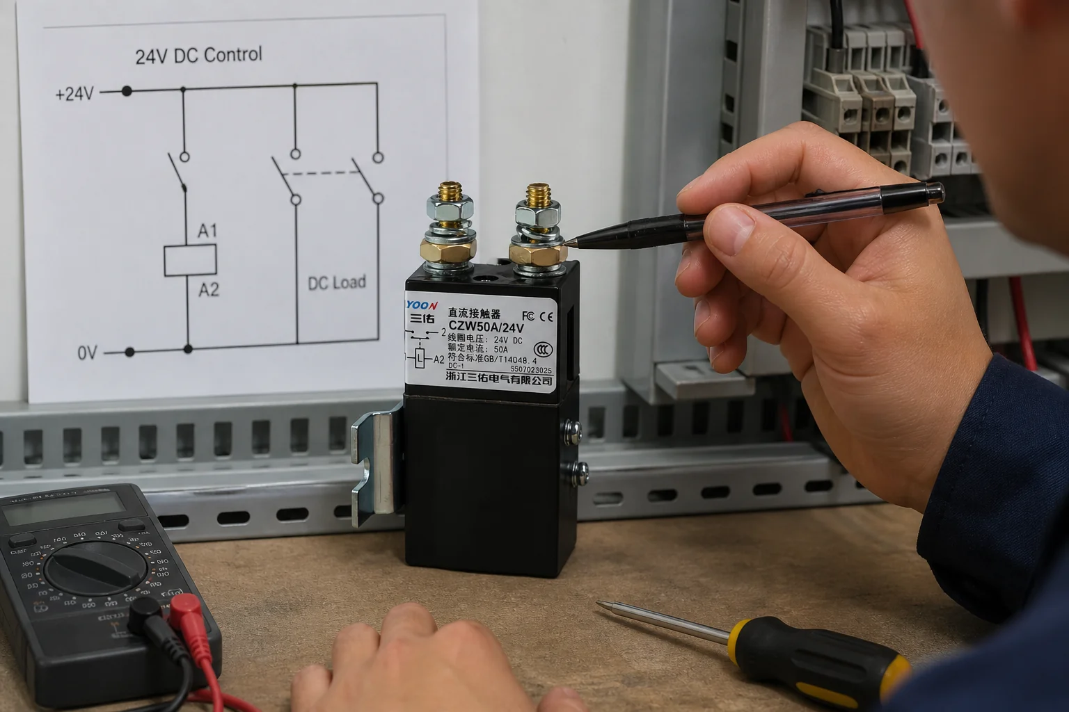
Finish with a product-document check: the schematic explains function; the selected model’s terminal diagram and contact form confirm the hardware. A symbol chart cannot authorize wire landings by itself.
From the field: When readers stall on a contactor drawing, they usually stall on the coil terminals or on whether a surrounding outline is “wiring” or just a device silhouette. Resolve the coil path first, then re-read NO/NC against the stated rest condition. Source: Garage Journal contactor schematic thread.
Practical verification order:
- Legend and normal condition
- Coil tag and cross-references
- NO/NC rest-state graphics
- Main versus auxiliary context
- Coil terminal marks versus power marks
- Model contact form on the datasheet or product drawing
Which SAYOON Product Fits an NO or NC Contactor Drawing?
Match the drawn contact form to a model that publishes the same form—CZW50A for a 1 NO path, or SZJB300A-D when the drawing needs a 1 NC path.
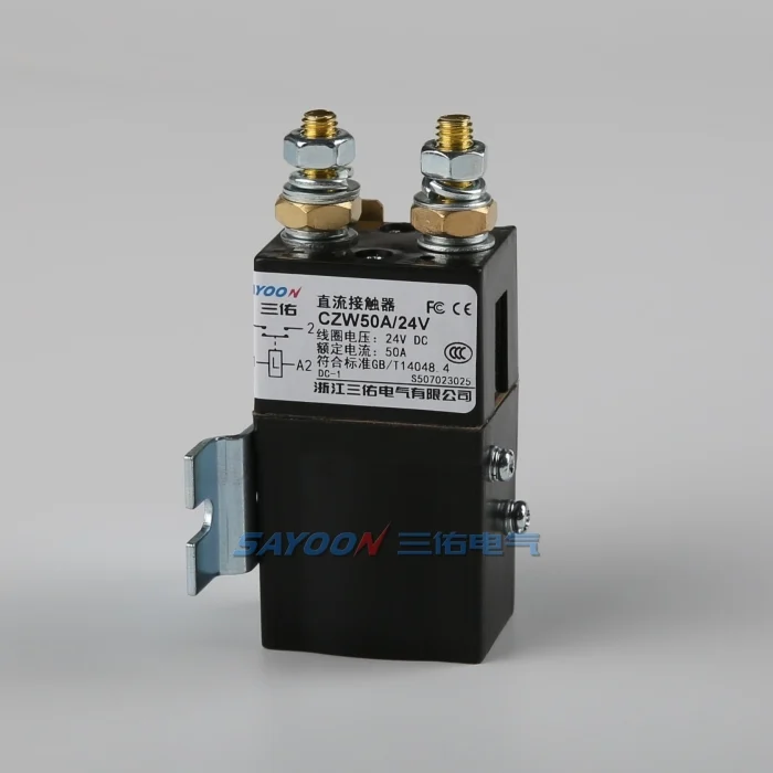
After the literacy checks above, open the product page for the candidate and confirm the contact form line. CZW50A normally open DC contactor lists contact form 1 NO on its public page, so it is a natural candidate when the main path is drawn normally open and the project conditions fit that model’s published scope.
When the schematic explicitly needs a normally closed main path, review SZJB300A-D normally closed DC contactor, which lists contact form 1 NC. Do not convert an NO drawing into an NC purchase—or the reverse—just because the current series looks familiar.
Browse the wider DC contactor products hub only after the drawing’s NO/NC and coil notes are settled. Symbol reading narrows the form; the datasheet finishes voltage, current, and coil selection.
FAQ
What is a DC contactor symbol?
It is the schematic encoding of a DC contactor’s coil and contacts. You read the coil identity first, then the contacts that share its tag.
How do you tell NO from NC on a contactor drawing?
Establish the drawing’s rest condition, then read the contact graphic: NO is open at rest; NC is closed at rest. Do not infer “normal” from the machine’s typical running state.
Why does a contactor coil symbol look different on IEC and ANSI drawings?
Drawing conventions differ. Many IEC contactor symbol libraries use a rectangular coil, while many ANSI/IEEE-style control drawings use a circular coil. Check the project legend.
What are A1 and A2 on a contactor?
They are the common coil terminal marks on many devices. They belong to the control circuit that energizes the coil, not to the main power poles.
Do main and auxiliary contacts use different symbols?
They often share NO/NC geometry. Weight, terminals, and circuit context show whether a contact is a power pole or an auxiliary path for the same coil tag.
Can you wire a contactor using only its schematic symbol?
No. Use the schematic for function, then confirm terminals, ratings, and contact form from the selected product documentation.
What does a mechanically linked contact mark mean?
When present, it identifies specially coordinated make/break contact elements that must not be closed at the same time under the defined conditions. It is not implied by every ordinary NO/NC pair.
Which SAYOON model matches a normally open contactor drawing?
For a published 1 NO contact form, start with CZW50A and confirm coil voltage and load conditions on that model’s page. Use an NC model such as SZJB300A-D only when the drawing truly needs a normally closed main path.
References
- Electrical Schematic Symbols Reference | IEEE C37.2 & IEC
- ANSI vs IEC Electrical Symbols Chart
- Auxiliary Contactors — mechanically linked contact marking
- Electrical Symbols — How to read electrical schematics? #3 Contactors
- Help interpreting wiring schematic for contactor (Garage Journal)
- Standardized power symbols? (EEVblog forum)





