A DC motor overspeed trip is a protective decision based on the configured speed information and machine limits. A DC contactor may be part of the resulting switching sequence, but it neither measures shaft speed nor proves that rotation has stopped. Investigate the original overspeed event, the controller’s requested action and the contactor’s actual response separately. Replacing a contactor without establishing those three facts can leave the initiating problem unresolved.
This guide is for maintenance teams and equipment buyers reviewing an existing motor system. It gives an evidence sequence rather than a universal trip setting or emergency wiring scheme. Motor, drive, load and machine instructions determine the permitted speed, stopping method and restart conditions. The Sayoon product photograph illustrates external construction only and does not establish suitability for a safety function.
Define which speed limit was exceeded
Start with the exact alarm wording, controller identity and software revision. An overspeed indication can refer to a configured operating limit, a feedback interpretation or a separately monitored machine condition. These meanings are not interchangeable. Keep the original event code and the applicable manual revision with the maintenance record so another engineer can reproduce the interpretation.
Write down the permitted speed from the approved motor and machine documentation. A process speed request, motor maximum speed and rotating load limit may serve different purposes. Do not take a percentage from another drive’s example and apply it to this machine. Where the existing documentation disagrees, keep the equipment unavailable until the responsible designer resolves the discrepancy.
Separate sensing, decision and switching
Speed information reaches a monitoring function through a defined sensing arrangement. That function evaluates a condition and requests a response. The contactor then changes a particular electrical path if the control design calls for it. Each stage needs a distinct record; a displayed trip does not establish that the downstream switching path opened correctly.
| Review item | Evidence to collect | Selection implication |
|---|---|---|
| Event | Exact overspeed code and permitted machine speed | Do not borrow a universal threshold |
| Measurement | Installed feedback identity and approved diagnostic evidence | Indication is not independently verified motion |
| Switching | Required command and independent response check | Command does not establish interruption |
| Release | Cause correction and authorized acceptance | Reset alone does not close the event |
Identify the relevant power path on the approved schematic. A contactor may control an upstream supply, an armature circuit or another designated path, depending on the design. Opening a particular path does not by itself establish complete isolation or immediate standstill. Avoid describing the whole machine as safe merely because one contactor is commanded off.

Preserve the operating sequence before reset
Record the speed request, indicated speed, load condition, operating direction and event time before clearing the alarm. Include whether the event occurred during acceleration, steady running, deceleration or a process disturbance. The sequence makes a maintenance report more useful than a photograph of the final alarm alone.
An operator may remember a noise or a sudden change in load, but record that as an observation rather than a confirmed cause. Preserve available trends and controller event records without recreating the fault. A repeated uncontrolled run is not an acceptable way to obtain better evidence. Qualified personnel should follow the site’s isolation and investigation procedure before inspecting the system.
Review feedback credibility before blaming switching
A speed display is information from a measurement chain. Confirm the installed feedback device, its configured interpretation and any separate indication available through an approved diagnostic method. A change in signal configuration or a damaged connection can undermine the meaning of the displayed value. This possibility does not justify ignoring a protective event; it defines another part of the investigation.
Distinguish a confirmed high shaft speed from a controller indication that has not yet been independently established. Document which evidence supports each conclusion. Where a qualified test is necessary, the machine owner must define the method and safe conditions. This article does not prescribe live probing, improvised sensors or a substitute protective channel.
Review field and drive information within their scope
For a separately excited DC motor, the field circuit and the drive’s operating instructions deserve explicit attention. The National MagLab explanation of DC motor action supports the relationship between magnetic field and motor operation, but it is not an industrial protection specification. Use the actual motor and drive documentation for fault handling and allowable operating conditions.
An overspeed fault must not be reduced to a shopping question about a larger contactor. Drive configuration, field information, mechanical load and feedback records belong in the same investigation package. A supplier can review the switching device only after the machine’s required switching duty is clear. Keep uncertain causes visible rather than treating the most easily replaced component as the diagnosis.
Confirm the required contactor response
Ask the responsible engineer to identify the expected sequence for this event: which command changes, which contactor responds and what independent indication confirms the resulting state. Some systems require an ordered stopping sequence; others use a different protective arrangement. Do not substitute a generic instruction to open every DC path immediately.
Compare recorded command information with approved response evidence. A coil command, an audible click and a status lamp answer different questions. None automatically demonstrates successful interruption of the intended load. If the command changed correctly but the response evidence is inconsistent, investigate the switching path using the product documentation and the machine’s authorized test procedure.
Keep electrical interruption distinct from standstill
A rotating assembly has mechanical behavior after electrical commands change. The required stopping time and any braking arrangement belong to the machine design. Do not promise that opening a contactor stops the motor instantly, and do not treat an off indication as proof that a rotating load cannot move.
The work permit and isolation process must account for all relevant energy sources. This includes conditions that the contactor does not control. The DOE motor systems sourcebook provides background on treating the motor and driven equipment together. It does not approve a particular stop sequence or replace the current installation instructions.
Decide whether replacement is supported by evidence
Replacement becomes a defined action when the contactor’s identity, required duty and observed defect have been established. Record the existing part marking, coil supply, connection arrangement and approved switching requirements. A photograph can help identify external construction, but it cannot establish interruption capability, mechanical life or functional safety suitability.
If the device responded as intended and the overspeed cause remains unresolved, replacing it does not close the incident. Conversely, confirmed switching damage needs attention even if the speed event originated elsewhere. Separate the corrective actions so that one successful repair cannot hide another open problem. Ask for written confirmation when product identity or current documentation is uncertain.
Prepare a useful supplier enquiry
Send the supplier the machine function, exact installed model, schematic excerpt approved for sharing, switching duty and a concise sequence of observations. State whether the question concerns coil response, contact condition, replacement availability or documentation. Avoid requesting a universal overspeed setting from a contactor supplier; speed protection belongs to the complete system.
A good request also identifies missing evidence. For example, the team may know that a trip command occurred but lack independent proof of contactor response. Describe that gap directly. The supplier can then explain which product documents or inspection information are available without being asked to infer a diagnosis from an alarm label alone.
Establish restart acceptance before returning to service
An alarm reset is an administrative step inside a larger acceptance process. Confirm the initiating cause has been addressed, the approved configuration is restored and the required protective response has been verified. Identify who may authorize restart and which evidence must remain with the maintenance record. A cleared display alone is not a release criterion.
Where the event followed a configuration or mechanical change, include that change in the acceptance review. Record any unresolved questions and keep them assigned to an owner. Do not silently reduce protective settings, bypass a monitor or rely on contactor replacement as proof that the system is ready. The final record should explain why the original event is now considered controlled.
Example: trip indication and correct switching response
Consider a machine whose controller records an overspeed event and requests its documented stop sequence. The switching response is independently confirmed, while the indicated speed trend remains inconsistent with another approved observation. This record supports investigating the measurement and control path. It does not establish that the contactor caused the speed indication.
A different case may show a valid protective command and an unconfirmed switching response. That case needs a switching investigation in addition to the speed review. The distinction helps purchasing avoid ordering a substitute before engineering has defined the fault. Neither example supplies a trip threshold or authorizes operation with a protective function disabled.
Educational video
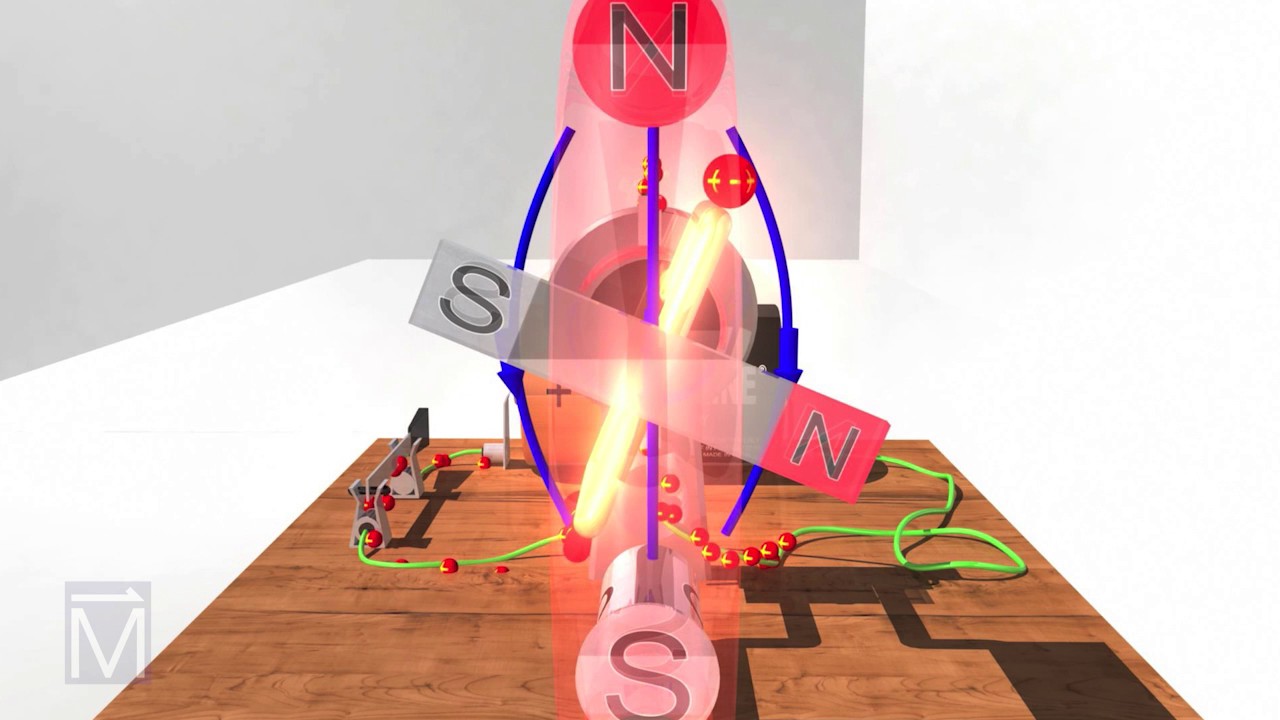
National MagLab explains basic DC motor action. This supplies physical background only; it does not define overspeed limits, encoder fault handling, blower requirements or protective switching sequences.
Frequently asked questions
Does an overspeed trip prove the DC contactor is faulty?
No. It establishes a reported protective event. The sensing information, controller decision and contactor response require separate evidence before a component diagnosis is justified.
Can I use a larger contactor to prevent overspeed?
A larger current label does not correct the speed control or feedback system. Define the cause and required switching duty before selecting any replacement.
Does opening the contactor prove the motor has stopped?
No. Electrical path state and mechanical standstill are different conditions. Use the machine’s approved stopping and standstill verification requirements.
Which speed should trigger the protective response?
Use the approved motor, drive, load and machine limits. This guide supplies no universal threshold, percentage or setting for a particular installation.
Product documentation and complementary guides
Use the CZQH300A-2T external-construction reference to discuss physical arrangement with Sayoon, and request current application-specific documentation before selecting it. Start with the DC contactor selection guide. Complementary subjects include DC Motor Reversing Contactors: Zero-Speed and Interlock Checks, DC motor plugging contactors: reverse torque and zero-speed cutoff, DC Contactor Coil Temperature Rise Testing.
Primary references and scope
The sources support the underlying physical or application principles described above. They do not establish a rating, certification or application approval for the pictured contactor.