A 180A DC contactor should be selected by its assigned carrying and switching duty, contact state and control-power-loss behavior. A part marked 180A or more does not automatically provide the required shutdown function. Normally open, normally closed and latching constructions can behave differently after a command or supply failure. Specify the circuit voltage, duration at load, making and breaking events, protection, coil options and feedback. This guide focuses on avoiding a wrong-state or wrong-duty replacement in a higher-current DC branch, using a normally closed product only as a clearly identified construction example.
Define the role of the high-current branch
Draw the branch that the contactor connects or disconnects, including every source, load and protective device. Identify whether the desired role is ordinary remote switching, maintaining a supply path, transferring between defined states or disconnecting after another device has cleared an abnormal event.
The 180A requirement should state its meaning and duration. A continuous load, short startup peak and fuse value are not equivalent. Record actual voltage range and load conditions together with current, so the supplier can assess the duty rather than only compare a nominal-current class.
Also describe the operational consequences of opening or reconnecting the branch. Equipment processes can require different responses to power loss. Those requirements determine which contact arrangement and control behavior deserve consideration before any product construction is treated as an acceptable candidate.
Choose the required main-contact state explicitly
For a conventional non-latching normally open device, the intact unoperated mechanism has an open main path. A normally closed device has a closed path in its defined unoperated state. A latching construction needs its own operating and reset description. None of those terms guarantees behavior after welding or mechanical failure.
A normally closed contactor held open by its coil can reconnect the main path when coil power is lost. That can be suitable for a documented function or unacceptable for a shutdown boundary. Do not substitute it for a normally open part merely because the current and dimensions match.
State the required main-contact position during normal operation, commanded stop, control-power loss and recovery. Keep auxiliary-contact state separate from main-contact state. This prevents a catalog “NC” signal terminal from being misread as the state of the high-current branch.
Assess carrying and interruption as different requirements
A 180A carrying requirement does not establish 180A DC breaking capability. Define current during opening, source voltage, load behavior, permitted direction and repetition. The contactor’s documented duty must match the events the equipment assigns to it.
A motor, converter or resistive branch can present different conditions at the same current. If another controller normally reduces current before opening, retain that sequence and assess the relevant failure cases. Do not silently extend the contactor’s role to full-load emergency interruption without supporting evidence.
For fault events, identify the protective device and coordination. The contactor may need to withstand a specified event until protection operates, rather than clear the fault itself. A higher nominal-current number does not resolve that distinction. Obtain evidence for the actual combination and circuit location.
Understand why small resistance deserves careful review
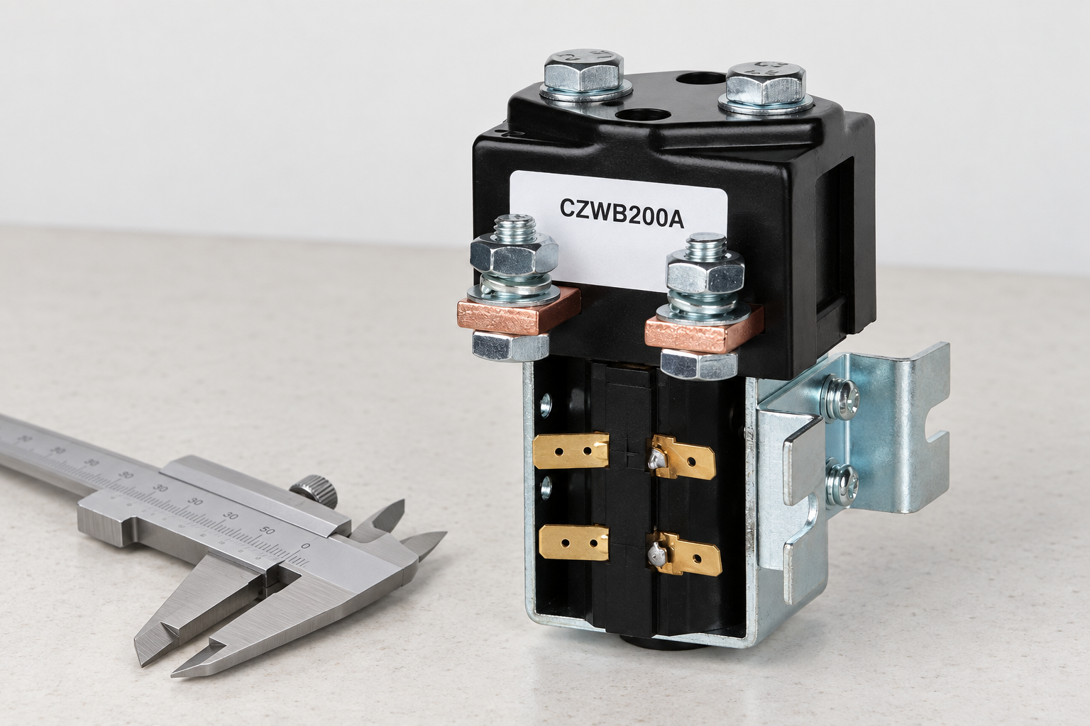
At higher current, local resistance can produce meaningful heating. For an illustrative 0.2 milliohm connection at 180A, P = I²R gives 6.48W, while V = IR gives 0.036V. The resistance is hypothetical; these results do not describe the pictured product or set a pass/fail limit.
The calculation helps explain why conductor joints and measurement conditions matter. Actual temperature depends on the installation’s heat transfer, current profile, ambient conditions and neighboring equipment. A single loss calculation cannot establish an acceptable contactor temperature.
Review terminal fastening, conductor construction and mechanical support using approved instructions. Investigate unstable or increasing voltage drop with a suitable controlled method. Do not compensate for a poorly assembled joint by assuming that a larger contactor class or extra airflow alone makes the branch acceptable.
Review the coil’s sustained state and supply recovery
Contact state affects how the coil is used. A normally closed main path that must remain open may require sustained coil operation; a normally open path held closed can also require sustained coil power. Determine pickup and holding demand from the exact variant instead of assuming one arrangement always consumes less energy.
Check supply range at the coil terminals, output-stage capability, polarity and suppression. Specify the expected behavior after a short dip or complete loss of control supply. Controller naming should describe the commanded equipment state clearly, particularly when coil-off means main-path-connected.
Review recovery and automatic restart separately. A contactor returning to its normal position does not decide whether the machine should resume operation. The equipment sequence, interlocks and fault assessment must define that response and be validated with the actual control arrangement.
Confirm main poles and auxiliary feedback
Identify each terminal and pole on the approved drawing. Main contacts carry the power load; auxiliary contacts provide lower-power indication or an interlock according to their own ratings. Do not treat an auxiliary continuity result as proof of the entire high-current path.
When feedback is important to the control sequence, obtain the documented relationship between auxiliary operation and main-contact behavior. The required diagnostic evidence depends on the assigned function. A general auxiliary output should not be described as a certified safety signal without the relevant evidence.
Compare a proposed replacement’s contact diagram with the actual equipment. Differences in pole form, default state or feedback timing can alter the sequence even when the new part fits. Include those changes in the design review and acceptance plan rather than treating them as harmless catalog variations.
Check the installation before interpreting a catalog margin
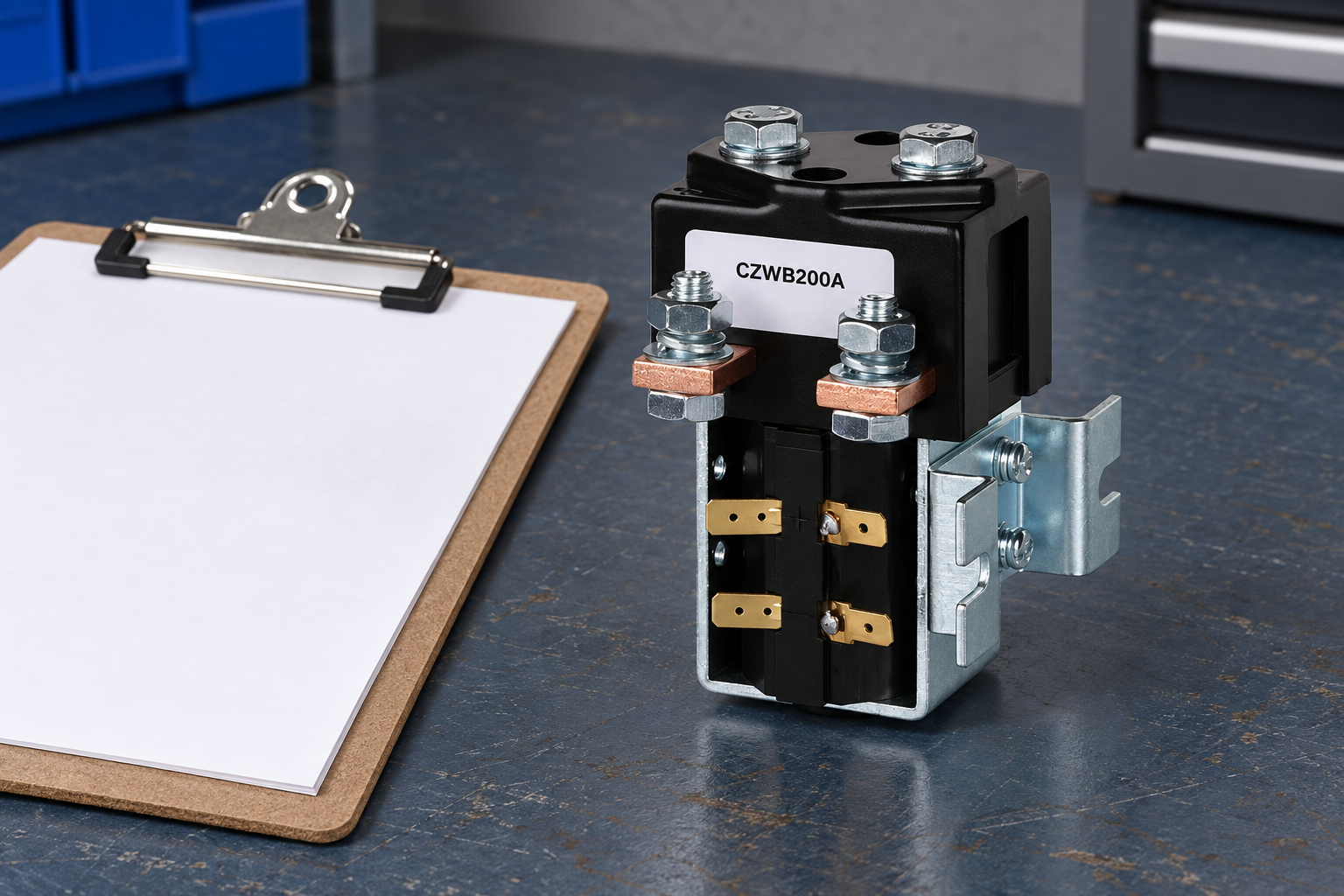
A nominal-current margin is useful only after the operating conditions and ratings are understood. Review enclosure temperature, conductor routing, lug geometry, mounting and protection against access or contamination. A contactor selected on an open bench must still meet the installed assembly’s requirements.
Obtain the manufacturer’s supported connection and mounting conditions. Do not infer torque, clearance or environmental approval from appearance. An open-frame or exposed-mechanism construction needs the appropriate equipment enclosure and installation assessment.
For sustained operation near the required branch current, plan representative thermal validation. Record ambient conditions, current duration and the actual conductor configuration. Keep the evidence attached to the installation drawing. If an enclosure, bracket or conductor arrangement changes later, review whether the original thermal acceptance remains applicable.
Release the ordering code only after the state review
Give the supplier the branch drawing, required states, voltage range, current profile, switching events, protection, control supply and feedback requirements. Identify whether 180A means continuous operating demand or another condition. Ask for supported duty evidence and an exact configuration, not just a larger current headline.
For a normally closed construction example, make the intended application boundary explicit. It is not a default recommendation for a battery emergency disconnect, nor proof that its release behavior matches a particular machine. Selection follows the approved state and fault assessment.
Retain identity, drawing revision, supplier evidence and validation with the purchasing record. Check delivered units against that record. If a replacement changes default state or coil behavior, review it as a design change before returning the equipment to operation, even if its nominal current is higher.
Selection evidence checklist
| Review field | Information to provide | Acceptance boundary |
|---|---|---|
| Branch role | Remote switching, maintained path or defined disconnect | State requirements come first |
| Normal state | MainNO/NC/latching arrangement | Do not confuse auxiliaryNC with mainNC |
| Power loss | Required branch position and restart response | NC can reconnect on coil-power loss |
| Switching duty | DC making and breaking conditions | 180A carrying alone is insufficient |
| Connections | Installed joints and conductor support | Assess heating under controlled conditions |
| Feedback | Documented main/auxiliary relationship | Do not infer safety proof from a signal |
This qualitative checklist organizes evidence; it does not state product ratings or universal acceptance limits. Numerical examples elsewhere are explicitly hypothetical.
Product information and related review tools
Das CZWB200A product information is the reference for the external construction shown. The pictured variant may have a different current class or contact arrangement from the requirement. It is not an automatic recommendation or a statement that every discussed duty is supported. Obtain the exact ordering code, drawing and applicable ratings before selection.
Benutzen Sie OEM specification evidence checklist to separate documented limits from unresolved assumptions. Complement the main-circuit review with coil voltage tolerance und mechanical versus electrical life. Those topics address distinct control and lifecycle questions rather than replacing this article’s assigned selection boundary.
Sources and safe validation
Scope references: IEC60947-4-1 contactor and motor-starter standard overview; U.S. electrical work-practice requirements. Apply relevant equipment requirements and approved manufacturer documentation. These links do not certify the illustrated product for a proposed duty. A commanded contact opening does not replace appropriate isolation and verification before servicing.
Educational contactor mechanism video
Electrician U explains the electromagnetic operating principle. This supports understanding of coil and contact operation, not a particular voltage, current, protection function or pictured variant’s qualification. The article’s selection evidence remains necessary whether or not the video is watched.

Häufig gestellte Fragen
Is a normally closed 180A contactor a drop-in battery disconnect?
No. Its default state and power-loss behavior must match the approved equipment design.
Does a higher current label prove stronger breaking capability?
No. Obtain the applicable DC interruption evidence for the assigned voltage, load and switching events.
Are 6.48W and 0.036V product limits?
No. They come from a hypothetical 0.2 milliohm connection example, not from product specifications.
Which replacement change deserves special attention?
A change in main-contact normal state, coil behavior or feedback can alter the equipment sequence even when the part fits.





