A 700A DC contactor must be selected for the actual current profile, maximum DC voltage, switching events and installed temperature. A 700A carrying requirement does not mean every device with a higher catalog current is suitable. Continuous carry current, short overload, making current and breaking current need separate evidence. Specify the exact operating conditions first, then compare the ordering code and its documentation against those conditions. For a battery-fed inverter, include capacitor charging and fault protection rather than treating the running current as the entire selection problem.
This guide is for equipment buyers reviewing a high-current DC connection. It shows how to turn a headline amperage into an RFQ that a supplier can answer and an engineer can verify. It does not assign an undocumented rating to any illustrated product.
Describe what 700A means in your installation
Start with a time-based load description. Record the highest continuous current, duration of overloads, rest periods and operating repetition. A demand lasting a few seconds and a demand lasting several hours impose different thermal conditions. State whether current flows during charging, discharge, regeneration or more than one mode.
Attach the enclosure temperature range and expected ventilation. The temperature around the device can differ substantially from room temperature, especially beside busbars or a converter. Ask which ambient and conductor conditions support the supplier’s carrying rating. If the supporting test used a different conductor arrangement, obtain an application assessment rather than assuming the same result.
Do not convert a short-duration rating into a continuous rating by averaging current. Average current alone does not describe resistive heating. For a changing load, give the waveform or a conservative sequence of current and time blocks so the supplier can evaluate its documented thermal limits.
Keep carry, make and break requirements separate
Carrying current describes the closed path. Making capability describes closure onto a specified circuit. Breaking capability describes interruption under stated conditions. A device can satisfy one requirement while failing another. The purchase specification should therefore contain separate rows for the three duties.
For normal opening, identify the current actually flowing when the contacts separate. A controller may reduce load before opening, but that sequence must be defined and confirmed. If the system also commands emergency opening at substantial current, include that event independently. Do not use a low-current normal opening test to justify the emergency duty.
Das IEC contactor publication record provides a route to the applicable standard. A standard reference is not product-specific proof. Ask for the exact tested configuration, operating conditions and any application limits.
Build a current-and-duty review sheet
| Prüfungselement | Input to record | Evidence or decision needed |
|---|---|---|
| Load profile | Continuous current, peak duration and repetition | Ask which documented carrying conditions cover the specified current and time blocks, including charging and discharge modes. |
| Operating voltage | Highest permitted main-circuit voltage | Compare maximum normal source voltage with supported operating and DC switching data; keep coil voltage separate. |
| Closing duty | DC-link charge state and precharge completion | Request evidence for the actual closure event and define how failed precharge prevents an uncontrolled main connection. |
| Opening duty | Current at normal and emergency opening | Ask for separate supported interruption conditions, including DC voltage, circuit characteristic, direction and repetition. |
| Thermal installation | Enclosure temperature and conductor arrangement | Compare supplier test conditions with mounting, ventilation, conductors and nearby heat sources; request an assessment for differences. |
| Terminals | Busbar interface and mechanical support | Obtain exact drawing, permitted hardware, fastening instructions and support requirements rather than using generic torque values. |
| Schutz | Available fault current and protective device | Identify what the contactor must withstand while the specified protective device clears a fault; request combination-specific evidence. |
| Control | Coil supply, suppression and feedback | Confirm pickup and holding demand, release behavior and driver compatibility for the exact ordered variant. |
Use this sheet with the electrical drawing. Mark unanswered cells as open questions. The purpose is to expose differences between your equipment and the supplier’s evidence before a purchase order makes those differences expensive.
Check the highest main-circuit voltage
Current and voltage are independent selection dimensions. Record maximum battery charging voltage or the highest supply condition that the contactor may encounter. A nominal battery voltage is not necessarily the highest normal operating voltage. Where two energy sources can feed the bus, identify their permitted operating combinations.
Check rated operating voltage separately from insulation and dielectric test values. A successful withstand test does not authorize switching at that test voltage. Require DC switching evidence at the applicable voltage and load characteristic. Changing to a larger current frame does not automatically solve an unsupported voltage requirement.
Define capacitor charging before main closure
An inverter DC link can draw a high transient when a discharged capacitor is connected to the source. The voltage difference, capacitance, resistance and source impedance affect the event. A contactor carrying 700A after closure has not thereby been qualified for uncontrolled capacitor charging.
Document the precharge path, the condition permitting main closure and the response to incomplete precharge. Avoid approving a fixed delay without validating it across permitted voltage and component conditions. Repeated failed starts can create a demanding sequence even if the running load remains within the thermal rating.
For background on charge storage, use the University of Texas capacitance discussion. The physical explanation helps define the circuit but supplies no rating for a particular switching device.
Confirm current direction and terminal orientation
Draw charging and discharge arrows. Some DC arc-control designs have polarity or interruption-direction restrictions. Conducting current through closed contacts in both directions does not establish that both interruption directions are qualified. The manufacturer’s documentation must address the assigned events.
Record which terminal receives each connection and how the installation will prevent reversal. If the equipment uses two contactors in series, do not assume they share open-circuit voltage equally. That assumption requires support from the circuit and insulation design.
Make the connection design part of the selection
At high current, electrical joints are part of the thermal problem. Obtain permitted conductor size or busbar requirements, terminal hardware, tightening instructions and mounting orientation. These are product-specific inputs; generic torque values are not a substitute.
A useful engineering illustration is P = I²R. At 700A, an assumed joint resistance of 0.0001 ohm would dissipate 49W. This is arithmetic using a hypothetical resistance, not a measured value or acceptance limit for a Sayoon device. It explains why a small connection resistance can matter and why installed testing must examine joints as well as the contactor body.
Do not support heavy cables from the terminal studs. Arrange mechanical supports and service clearances from the installation drawing. A cable that twists a terminal can create a problem that cannot be corrected by selecting a larger amperage label.
Coordinate overload and fault protection
Identify the protective device assigned to clear a fault and the available fault current at the installation point. Routine connection duty and fault interruption are different functions. Ask what the contactor must carry or withstand until the protective device operates and whether it has any specifically documented fault-opening assignment.
Use the actual protective-device combination and evidence. A fuse’s rating alone does not demonstrate contactor coordination. Record the sequence after a fault and the conditions for inspection or replacement. An automated restart should not bypass an unresolved welded-contact or insulation concern.
Review the coil as a separate circuit
The main current rating does not identify coil voltage. Specify control supply type, nominal voltage, lowest available voltage at the coil and any permitted suppression or economizer arrangement. Include pickup demand and holding demand where relevant to the driver.
Check behavior during control supply loss and recovery. The device’s return state, release time and feedback relationship should match the equipment’s intended sequence. External suppression can affect release behavior; do not add components without reviewing the exact variant’s instructions.
Validate a sample without improvising a live test
Begin with identification and dimensional checks while isolated. Compare the ordering code, contact arrangement, terminals and mounting with the approved drawing. Then use a qualified test plan for coil behavior, closed-path resistance and installed thermal performance. Select instruments and test conditions suitable for the equipment.
High-current making and breaking tests require appropriate facilities, protection and personnel. They are not a bench exercise to improvise from an online guide. Apply the requirements relevant to your location and task.
Send a specific RFQ and close the open decisions
Send the operating voltage range, current-time profile, load type, precharge sequence, assigned opening events, direction, enclosure temperature, conductor arrangement, coil supply and required evidence. Request the exact ordering code and drawing revision. Ask the supplier to identify exceptions instead of answering only with a price.
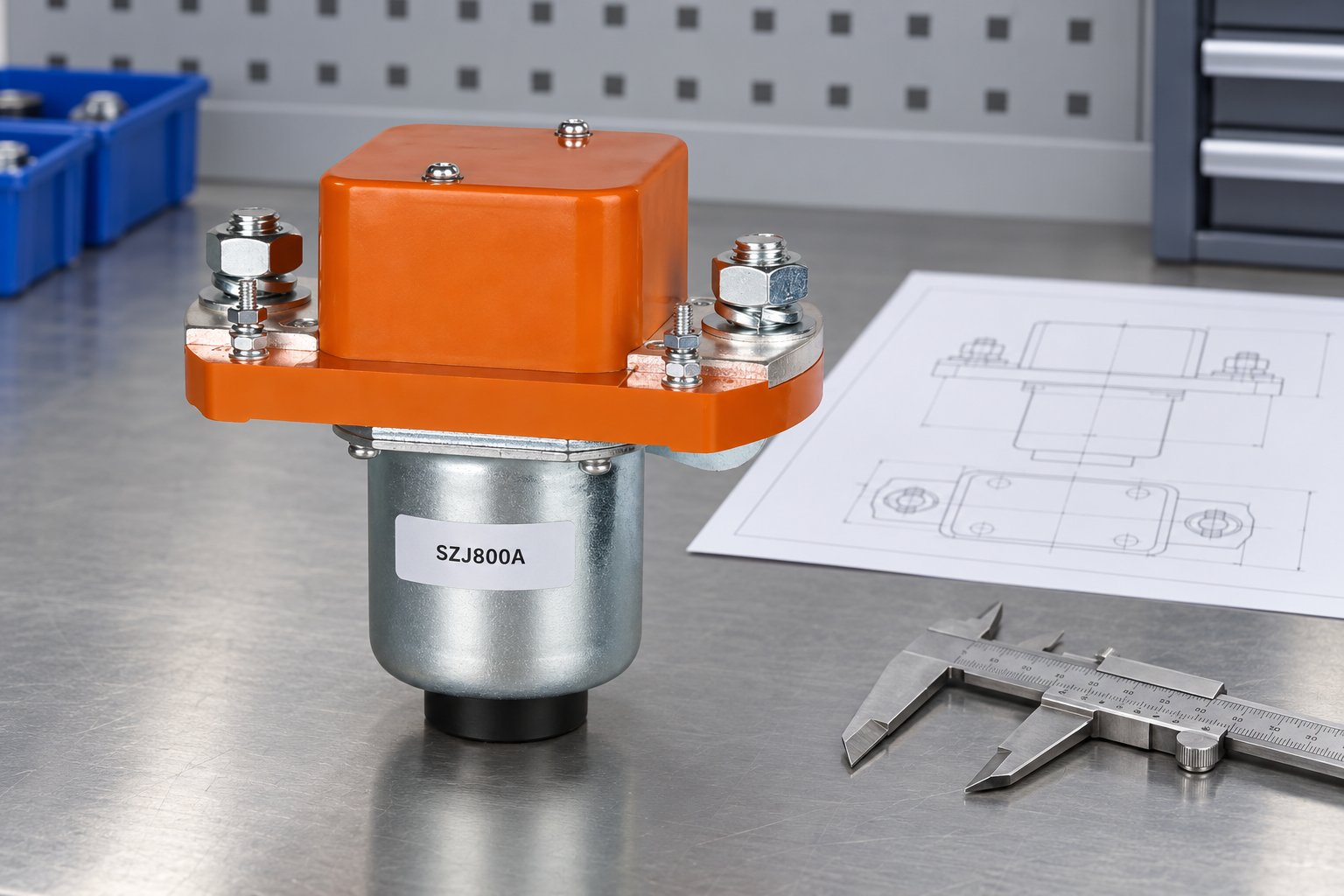
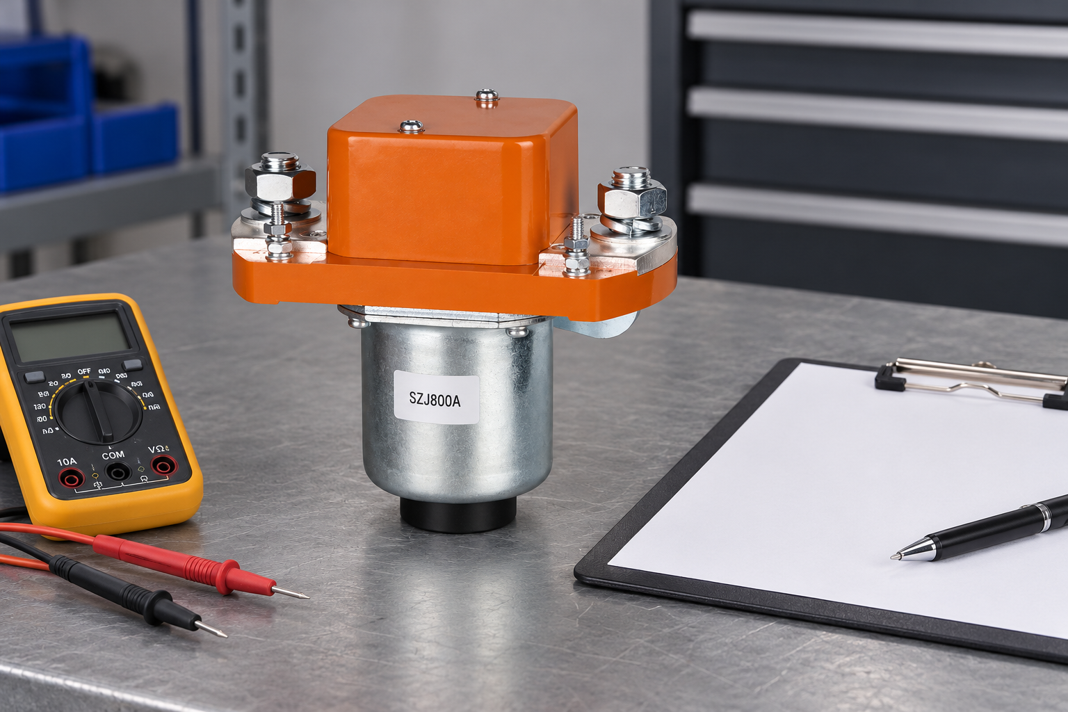
Das illustrierte SZJ800A Schließer DC-Schütz provides a construction reference for discussion with Sayoon. Its photograph does not establish suitability for 700A operation or any DC breaking duty. Obtain the exact applicable variant and written evidence before approval.
Benutzen Sie DC contactor current-selection hub for the wider selection framework, the temperature derating guide for installed heat considerations, and the BESS thermal monitoring guide for complementary operating observations. Keep these reviews connected to one approved specification rather than treating each page as a separate product qualification.
Educational video: contactor operation
The educational video below explains contactor operation. It supports understanding of the coil and contacts, but does not qualify a device for 700A or replace the required current, voltage and interruption evidence.

Watch the Electrician U educational explanation on YouTube.
Häufig gestellte Fragen
Does a 700A carry rating mean the contactor can break 700A?
No. Carrying and breaking duties require separate documented conditions, including DC voltage, circuit characteristics and repetition.
Can I select an 800A device for a 700A load?
Only after checking its documented conditions against the complete installation. A larger headline current is not independent proof of voltage, thermal or switching suitability.
Which current should appear in the RFQ?
Provide continuous current, overload duration, charging and discharge modes, making events and current at each assigned opening event.
Does the illustrated product prove application suitability?
No. The image illustrates construction. The exact ordering code and supporting application evidence determine suitability.





