Schnelle Antwort: An AGV battery contactor must match the complete DC-link duty, not just cruising current. Confirm maximum battery and charger voltage, traction and lift current, capacitor inrush and precharge, regenerative current direction, opening current, fault protection, coil supply, feedback, switching life, vibration, contamination, and thermal conditions. Then validate the exact contactor, driver, conductors, fuse, controller logic, and enclosure on a production-intent AGV.
This guide turns agv battery contactor into a reviewable engineering and service workflow. It uses authentic Sayoon product photography while keeping every application decision tied to the final machine, current product documents, applicable standards, and representative testing.
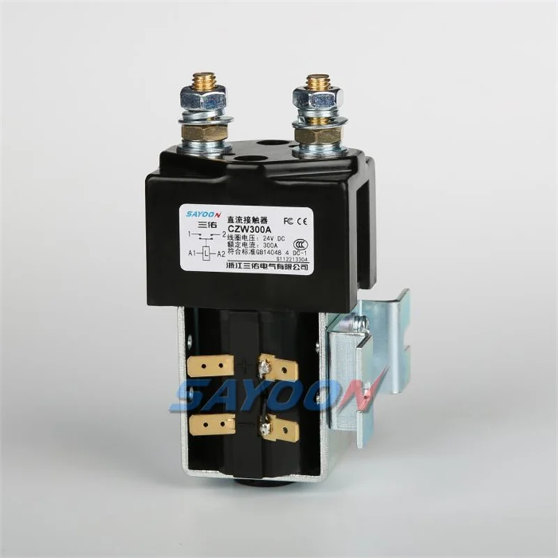
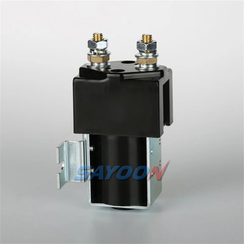
Decision table
| Operating condition | Likely electrical or thermal concern | Required check |
|---|---|---|
| Power-up | Precharge charges controller capacitors before main closure | Verify bus-voltage ratio and prevent closure after failed precharge |
| Driving and lifting | Bidirectional or combined traction/auxiliary current | Use measured route and payload duty |
| Regenerative braking | Current may return toward battery | Confirm current direction and opening strategy |
| Emergency or service isolation | Stored energy and possible charger/back-feed remain | Define boundary, discharge and independent verification |
Produktreferenz und Anwendungsbereich
Das CZW300A normally open DC contactor is a real product reference, not automatic approval for a particular machine. Use the DC contactor guide hub und selection guide for adjacent decisions. Confirm the complete ordering code, current direction, make and break duty, coil, feedback, insulation, environment, mounting, protection, and life.
Define the disconnect boundary
Draw the battery, positive and negative devices, precharge branch, motor controllers, lift system, DC/DC converters, charger, service connector, sensors, and every path that can energize the bus. State whether one or two contactors are required and which terminals remain live after opening.
A fleet charger, tow mode, external service supply, or controller capacitor can change the safe state. Auxiliary feedback indicates mechanism position, not absence of voltage. Use voltage and current evidence at the actual service boundary.
Control inrush with a verified precharge
Estimate DC-link capacitance only as a starting point, then measure the assembled AGV. The controller should close the precharge path, verify the expected voltage rise within bounded time, close the main contactor only after the acceptance condition is met, and then remove or bypass the precharge path as designed.
Detect an open resistor, welded precharge contactor, excessive capacitance, shorted controller, wrong sensor, and timeout. Repeated failed attempts can overheat the resistor and contactor, so limit retries and preserve diagnostic evidence.
Include regeneration and charger states
Traction drives can return current during deceleration, downhill travel, or load lowering. Confirm whether the contactor must carry or interrupt current in both directions and how the controller removes regenerative torque before opening.
Include autonomous charging, opportunity charging, manual disconnects, communications loss, emergency stop, and recovery. Define what occurs if charging is active when a stop is requested or if the AGV reaches a charger with a welded main device.
Capture the real operating profile
Measure battery voltage from its lowest approved state to maximum charging voltage, current during pickup and steady operation, current direction, event duration, switching frequency, and the time available for cooling. Include cold oil, steep ramps, stalled mechanisms, blocked wheels, regenerative braking, charger connection, and emergency stops where applicable.
Do not size from a motor nameplate or one clamp-meter snapshot. Controller limits, cable resistance, battery condition, hydraulic pressure, operator behavior, route gradient, payload, and temperature change the duty. Preserve synchronized voltage, current, command, feedback, and temperature records from representative equipment.
Separate carrying, making, and breaking duty
Continuous-current capability describes thermal carrying under stated conditions; it does not automatically prove the device can close into motor or capacitor inrush or interrupt the expected DC current. Specify the voltage, current direction, inductance, time constant, available fault current, and upstream protection for every switching event.
Normal control should reduce current before opening when the machine architecture permits. Emergency and fault cases need their own protection sequence. A fuse or breaker may clear duties that a control contactor is not intended to interrupt, so coordination must be documented for the exact installation.
Match the coil and driver
Confirm nominal coil voltage, pickup and dropout behavior across the full auxiliary-supply range, pull-in and hold current, economizer behavior, suppression, polarity where relevant, and the longest approved harness. Measure voltage at the coil while it is energized, not only at the controller.
A flyback diode, TVS, economizer, or driver clamp changes release time and electrical stress. Low voltage can cause chatter and heating; excessive voltage can overheat the winding. Use product-specific limits and validate the complete controller, connector, cable, coil, and suppression path.
Design the mechanical and thermal installation
Check mounting orientation, vibration, shock, contamination, moisture, ventilation, proximity to heat sources, cable support, busbar alignment, terminal hardware, conductor cross-section, bend force, and service access. The enclosure and adjacent hot components can reduce cooling compared with an open bench.
Use the specified hardware and controlled tightening procedure. Do not use a terminal stud to pull a misaligned cable into place. After assembly, inspect washers, thread engagement, lug seating, barriers, strain relief, and clearance. Recheck representative units after the approved commissioning cycle.
Use feedback as one layer of evidence
An auxiliary contact can indicate mechanism position but cannot prove low resistance through the main contacts or absence of voltage. Correlate command, coil current, auxiliary state, main current, and voltage on both sides of the switching boundary within validated timing windows.
Define responses for stuck-open, delayed pickup, chatter, welded contacts, broken feedback wiring, driver faults, sensor faults, and unexpected back-feed. Preserve the first fault snapshot and prevent automatic restart when isolation or switching state cannot be proven.
Validate before release
Test production-intent contactors, controllers, conductors, protection, sensors, cooling, and software. Cover low and high supply, cold and hot operation, maximum approved load, repeated cycles, longest harness, and representative abnormal cases. Use rated instruments and an authorized safety procedure.
Record complete part numbers, drawings, firmware, sample identity, ambient and component temperatures, waveforms, instrument settings and calibration, acceptance limits, deviations, and reviewers. A successful bench close-open test is not evidence for the full vehicle duty.
Prepare the RFQ and change-control record
Provide voltage range, current waveform and direction, make and break events, fault current and protection, coil supply and driver, feedback, duty cycle, life target, environment, mounting, conductors, terminal hardware, standards, and required evidence. Ask which values apply to the exact order code.
Reopen the decision after changes to the battery, motor, pump, inverter, controller firmware, cable, fuse, suppression, cooling, enclosure, route, payload, or maintenance method. Visually similar replacements are not interchangeable until the same electrical, mechanical, thermal, and control checks pass.
For fleet deployment, create a controlled acceptance sheet that technicians can use without guessing. It should identify the machine configuration, battery and controller versions, exact contactor code, approved conductors and hardware, inspection points, required waveforms, temperature and timing evidence, fault-injection results, and sign-off authority. Compare a pilot installation with a healthy reference vehicle over representative routes and loads before broad release. Retain removed parts and event data long enough to complete failure analysis. Training should explain which symptoms require immediate isolation, which measurements are permitted, and which changes must return to engineering review.
Route-specific evidence should also cover docking impacts, charger transitions, steep ramps, payload variation, and repeated autonomous recovery attempts.
Safe inspection and maintenance
Treat the battery, controller capacitors, charger, parallel supplies, and test equipment as hazardous energy sources until an authorized person has applied the site procedure and verified the required state with rated instruments. Do not bridge an interlock, force a coil, tighten a live terminal, or open a device outside its qualified switching duty. After replacement, repeat approved pickup, load, stop, isolation, feedback, and restart-inhibit checks before returning the machine to service.
Verwandte Sayoon-Anleitungen
Review the 48 V forklift contactor application guide, AGV and forklift reversing-contactor guide, coil temperature-rise test guide, und high-current terminal torque guide. These cover complementary decisions and should not be used as substitutes for the exact product data.
Lernvideo
Was ist ein Schütz und wie funktioniert es? by Electrician U provides neutral visual background on contactor operation. It does not replace product documents, machine measurements, protection studies, or safety procedures.
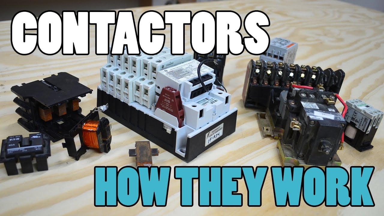
Sieh dir das Lernvideo auf YouTube an.
Häufig gestellte Fragen
What is the first check for agv battery contactor?
Confirm the exact circuit, operating state, voltage, current waveform, duty cycle, and approved product configuration before comparing ratings.
Can nominal motor current select the contactor?
No. Include starting, stall, regeneration, opening, repetition, temperature, installation, control, protection, and required life.
Can auxiliary feedback prove safe isolation?
No. Correlate command and feedback with current and voltage measurements across every possible energy path.
Was sollte eine Angebotsanfrage enthalten?
Provide the complete electrical waveform, environment, mounting, coil driver, feedback, protection, life target, standards, and validation requirements.
Zuverlässige Referenzen
- OSHA 1910.147 – Kontrolle gefährlicher Energie
- OSHA 1910.178 — powered industrial trucks
- IEC 60947-4-1 — Relais und Motorstarter
- NIOSH — powered industrial truck inspection
Use the standards and editions adopted by the project. Confirm current requirements and the exact product evidence before approval.





