An intermittent DC contactor fault appears only under certain conditions, so a normal bench check may not reproduce it. Separate an unintended intermittent malfunction from a contactor that is deliberately rated for intermittent duty. Diagnose the malfunction by recording the operating condition, requested state, actual response and relevant control evidence for both a successful cycle and a failed cycle. Look for a repeatable difference before replacing parts. Work from saved logs and safely isolated inspections first; any necessary energized measurements require qualified people, suitable equipment and an approved procedure. A disappearing symptom is not proof that its cause has been corrected.
Clarify what intermittent means in the service request
A catalog description such as intermittent duty describes a permitted operating pattern under specified conditions. It does not mean that the device should fail unpredictably. Obtain the exact duty information for the ordered variant before deciding whether the installation is appropriate. Do not infer a permitted on-time, rest period or switching frequency from an online listing for a similarly named product.
For a service problem, write the observable symptom instead: sometimes fails to close, opens unexpectedly after warming, operates only after a reset, or reports a feedback fault. State the expected response and how the actual response was observed. That distinction keeps a search for duty-cycle information from being mistaken for evidence about the particular failure.
Define the failure and the successful comparison
Choose a clear event boundary. For failure to close, record when the command was requested and what confirmed closure was expected to look like. For an unexpected opening, preserve the preceding operating state. For repeated rapid cycling, use the dedicated chattering diagnostic record rather than treating every click as a separate intermittent failure.
A useful comparison includes a successful cycle from the same equipment configuration. Record source condition, ambient or enclosure state, load phase, time since startup and relevant commands for both cases. Do not change several components between the two observations and then claim that one of them was responsible. Keep configuration revisions and previous maintenance visible in the record.
Preserve evidence before a reset or reseating a connector
Save fault codes, controller logs and operator observations before clearing the condition. Mark the time accurately enough to compare separate records. A communication interruption, driver reset or shared-supply disturbance may leave evidence in another subsystem rather than in the contactor controller itself. Ask which logs survive a power cycle and export them using the approved equipment interface.
Avoid immediately unplugging every connector or tightening all terminals. These actions can temporarily change a poor connection and remove the most useful clue. When corrective work is necessary, document the original condition first under a safe procedure. Label each deliberate change and retain the removed component when a supplier or engineering investigation is still open.
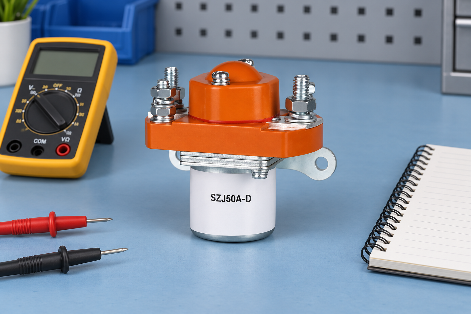
Begin with safe external inspection
An authorized person should isolate the equipment, control stored energy and verify the work area before opening covers or touching connections. A controller stop command is not safe isolation. 29 CFR 1910.333 provides a US workplace reference for electrical work practices within its scope; follow the applicable local requirements and equipment instructions.
Inspect accessible wiring, connector retention, strain relief, contamination, mounting and visible damage against the approved drawing. Record what is actually observed. A connector that looks secure can still need an approved electrical assessment, while a discolored surface does not by itself identify the initiating cause. Do not tap, shake or disturb energized high-energy equipment to reproduce the fault.
Follow the command from software to the physical driver
Compare the requested contactor state with interlocks and permissive conditions. A controller can be behaving as designed when an intermittent sensor, communication link or protection condition changes. Establish whether the requested state changed before the observed contactor response. If the command disappears first, investigate the initiating input rather than immediately condemning the contactor.
Then distinguish a displayed software command from the physical driver output. Intermediate relays, connectors, wiring and driver protection can interrupt delivery to the coil. Record the actual observation point and its limitations. Never bridge an interlock, bypass feedback or suppress a fault merely to make the equipment run longer; the responsible designer must evaluate any proposed control change.
Compare coil conditions at the relevant time
Review whether an approved record captures the coil-terminal supply during the failing event, rather than only the upstream power supply during normal operation. A short disturbance can be invisible on a slow meter display. If additional data are needed, define the required timing and method before arranging a qualified test. An unsuitable measurement can create false confidence while missing the event.
Use the exact coil and driver documentation to interpret the result. Electronic or economized devices may have a controlled holding profile that differs from a simple coil. The coil cable voltage-drop guide addresses one possible control-path issue. It does not establish that every intermittent event is caused by voltage drop, and no universal voltage percentage is supplied here.
Use a comparison matrix instead of a parts-swapping list
The table below helps assign evidence to competing explanations. It deliberately provides no universal numeric limits. Record the configuration and the source of each observation; a correlation should direct the next controlled check rather than automatically establish a defective component.
| Prüfen | Verlangte Beweismittel | Entscheidung oder Dokument |
|---|---|---|
| Cold successful, warm failure | Operating duration, relevant temperatures, supply and driver state | Review temperature-related conditions without assuming that the coil is the cause. |
| Failure follows another load starting | Shared source, load sequence and control timing | Check for a common supply or programmed interaction. |
| Command changes before the symptom | Interlocks, protection inputs and controller logs | Investigate why the command changed. |
| Command appears steady at software level | Physical driver and coil-terminal evidence | Distinguish requested output from energy actually delivered. |
| Problem changes after maintenance | Exact parts, connectors and wiring revisions | Compare the as-found configuration with the approved configuration. |
| No fault during a bench check | Bench conditions and actual field conditions | State what the check excludes and what remains untested. |
| Symptom disappears after reseating | Before/after connection evidence and controlled follow-up | Treat the change as a clue, not a complete root-cause finding. |
Review temperature, vibration and installation conditions
Use records to determine whether the failure correlates with warm-up, enclosure conditions, movement or another operating phase. Correlation can identify a useful investigation direction, but several components may share the same environment. A thermal condition can affect a driver or connection as well as the contactor. Keep the system boundary wide enough to include the evidence.
Review the documented mounting and environmental requirements for each relevant component. Do not loosen mounting, add cooling or alter the enclosure without assessing the consequences. Any controlled environmental or vibration investigation needs an appropriate plan and equipment; an improvised field stress test can cause damage and still fail to represent the original condition.
Use measurements with a defined purpose
Write down the quantity and conditions needed to distinguish the remaining hypotheses. NIST-Richtlinien zur metrologischen Rückverfolgbarkeit explains why the evidence behind a result matters. Instrument calibration is one part of that evidence; timing, connections and suitability for the quantity also affect the interpretation.
A resistance check after cooling and a time-aligned supply record during operation answer different questions. Keep them separate in the report. Do not apply the temperature-aware coil-resistance method to an electronic assembly without checking its permitted procedure. When a test cannot resolve the cause, report the limitation and the evidence still needed.
Verify one justified correction at a time
Choose corrective work from the evidence and obtain the required authorization. Record the exact change, part identity and procedure revision. Replacing several unrelated items can restore service while leaving the cause uncertain; if operational constraints require that approach, state the resulting limitation rather than presenting a proven single-component diagnosis.
Verification should cover the conditions associated with the original problem and any required safety or functional checks. Define the duration or number of observations in the approved plan using the equipment requirements, not a universal cycle count. If the symptom is rare, the report should distinguish no recurrence observed from a demonstrated root cause and verified correction.
Prepare a useful supplier failure package
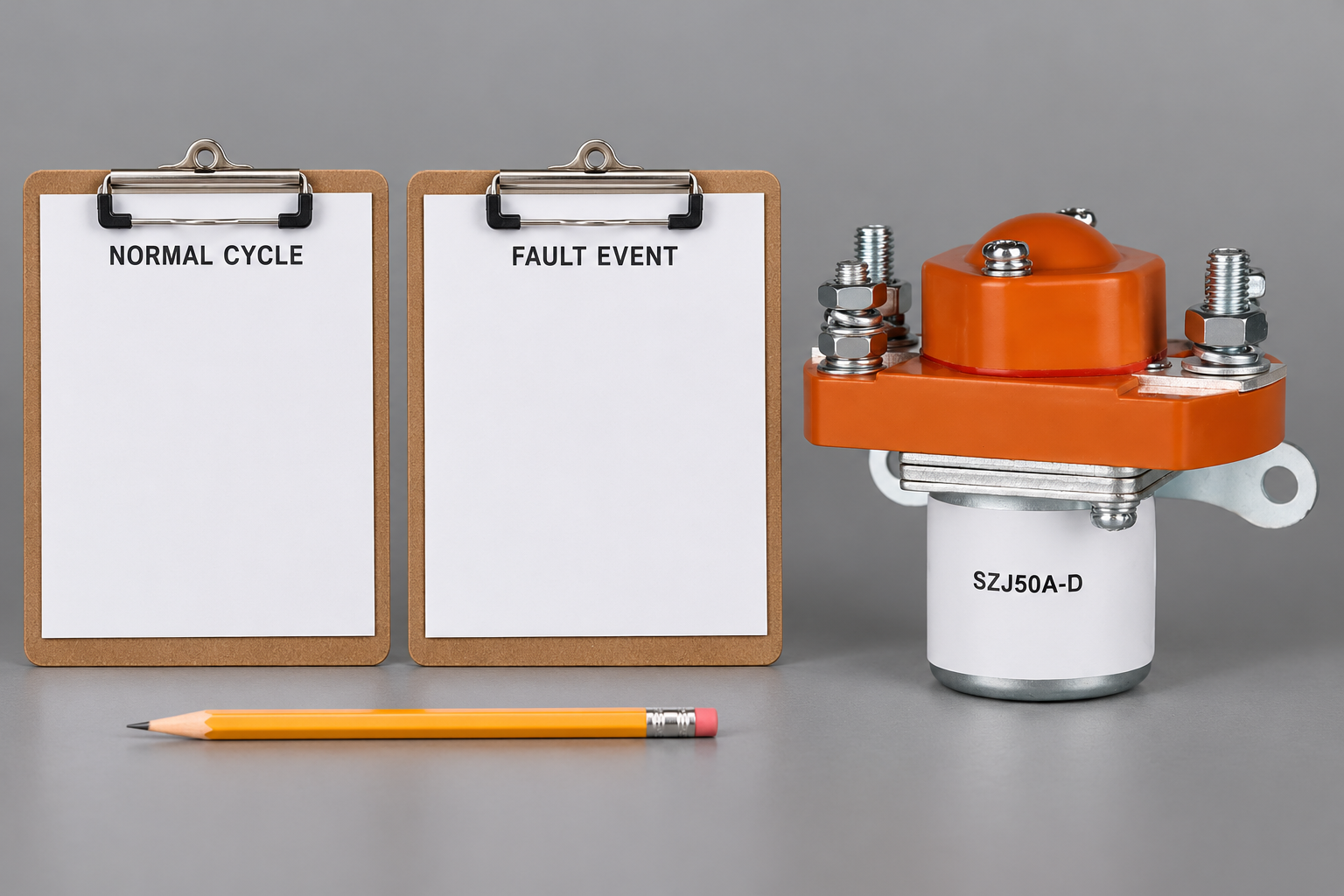
The pictured SZJ50A-D Schließer Gleichstrom-Schütz is an external construction reference, not evidence of an intermittent-duty rating or suitability for the described equipment. Include the exact ordering code, coil option, original event record, wiring and driver details, operating conditions and work already performed when contacting Sayoon.
Benutzen Sie Hub zur Auswahl der Spulenspannung to organize the control requirements. Identify whether the inquiry concerns application selection, a field failure or a requested document. Preserve the unit for any agreed return analysis and keep the equipment release decision with the authorized owner. Clear evidence is more valuable than a request to replace a part because it sometimes works.
Bildungsvideo: Die Kontaktaufnahme verstehen
Die nachfolgende Erklärung des Elektriker U erläutert, wie eine Spule Kontakte aufweist. Nutzen Sie sie, um die Unterscheidung zwischen Steuerung und Hauptschaltkreis zu verstehen, bevor Sie sich die Inspektionszeichnung ansehen. Sie vermittelt allgemeine Informationen und keine Testverfahren oder die Genehmigung des dargestellten Sayoon-Modells.

Schauen Sie sich die Bildungsanleitung „Elektriker U“ an.
Häufig gestellte Fragen
Does intermittent duty mean unreliable operation?
No. Intermittent duty is a specified operating pattern. An intermittent malfunction is an unintended response that requires its own evidence.
Can a normal bench check rule out the field fault?
No. State which conditions were checked and compare them with the actual failing condition.
Does reseating a connector prove the root cause?
No. It is a useful clue, but the connection condition and controlled follow-up still need evaluation.
Should several parts be replaced at once?
Use evidence to select corrective work. If several items are changed, disclose the resulting limits on identifying the cause.





