Contactor duty cycle describes how long and how often the coil and main contacts are energized or switched. Continuous duty, intermittent duty, and repetitive short-time service impose different thermal and wear demands. Do not translate a simple on/off percentage directly into an acceptable rating. Specify on-time, off-time, starts per hour, switching current, load type, ambient temperature, enclosure, and required life, then obtain product-specific approval. This article explains a controlled review method; it does not replace the selected contactor’s data sheet, applicable standards, or a qualified electrical safety assessment.
Puntos clave de revisión
| Elemento de revisión | Evidencia a recopilar | Por qué importa |
|---|---|---|
| On-time | State the longest energized interval | Average percentage can hide a long thermal soak |
| Off-time | State minimum cooling interval | Short pauses may provide little cooling |
| Operations | Record starts per hour and total life target | Contact wear follows switching events |
| Load type | Identify resistive, motor, capacitive, or inductive load | Making and breaking stress differs |
| Medio ambiente | Record ambient, enclosure, airflow, and altitude | Thermal margin depends on installation |
Coil duty and contact duty are separate
The coil may remain energized while the main path carries steady current, or it may switch frequently with short energized intervals. Coil heating depends on voltage, control strategy, ambient temperature, and hold-power design. Main-contact heating and erosion depend on current, joints, load transients, and operations.
Aplique este punto al rango operativo real en lugar de a una condición nominal de banco. Registre tanto el estado ordenado como la respuesta medida, anote cualquier acción del controlador o de protección, y conserve la evidencia que otro revisor pueda reproducir. Si la documentación del producto no indica el límite necesario, considere la selección como no resuelta y solicite al fabricante una confirmación por escrito.
Why a percentage is incomplete
Fifty-percent duty could mean one minute on and one minute off, or twelve hours on and twelve hours off. Those cycles produce different peak temperatures and numbers of switching events. A complete duty profile includes timing, current waveform, overloads, expected cycling, and the worst operating day.
Aplique este punto al rango operativo real en lugar de a una condición nominal de banco. Registre tanto el estado ordenado como la respuesta medida, anote cualquier acción del controlador o de protección, y conserve la evidencia que otro revisor pueda reproducir. Si la documentación del producto no indica el límite necesario, considere la selección como no resuelta y solicite al fabricante una confirmación por escrito.
How to validate the selected contactor
Review the manufacturer’s duty statements and test the actual enclosure at worst-case supply, load, and ambient conditions. Monitor coil voltage, case and terminal temperatures, voltage drop, release behavior, and surrounding cable temperature. Accelerated testing should not introduce failure modes that the real application never sees.
Aplique este punto al rango operativo real en lugar de a una condición nominal de banco. Registre tanto el estado ordenado como la respuesta medida, anote cualquier acción del controlador o de protección, y conserve la evidencia que otro revisor pueda reproducir. Si la documentación del producto no indica el límite necesario, considere la selección como no resuelta y solicite al fabricante una confirmación por escrito.

Cómo convertir el tema en una decisión de ingeniería
Comience con el esquema aprobado, el dibujo del producto y la secuencia de operación. Registre el voltaje de control mínimo y máximo, el voltaje del circuito principal, la corriente normal y anormal, la frecuencia de conmutación, el rango ambiental, el gabinete, el montaje, las interfaces de los conductores y los dispositivos de protección. Un número de pieza corto o un valor de amperaje principal no pueden representar todas esas condiciones.
A continuación, separe la observación de la interpretación. Un retraso, temperatura, caída de tensión o resistencia observados son datos. La causa propuesta es una hipótesis que requiere una comprobación controlada. Cambie una variable a la vez cuando sea práctico, conserve los detalles del instrumento y de la configuración, y compare el resultado con los criterios exactos del fabricante. Esto evita que un fallo de cableado, una fuente de control débil, un terminal flojo o una carga inadecuada se diagnostiquen erróneamente como un contactor defectuoso.
Por último, revise el resultado a nivel de sistema. Un cambio que mejora un comportamiento puede empeorar otro: una supresión de sobretensiones más fuerte puede retrasar la liberación; una cámara sellada puede alterar el comportamiento térmico; un controlador de bobina de menor potencia puede reducir el margen de activación; y un contactor con una corriente de transporte amplia aún puede carecer de la evidencia de ruptura requerida. La aprobación pertenece a la combinación completa de dispositivo, controlador, carga, protección, instalación y lógica de funcionamiento.
Flujo de trabajo de verificación antes de la aprobación
- Define el estado. Marque qué fuentes están aisladas, dónde permanece la energía almacenada y si la prueba concierne a la bobina, a los contactos auxiliares o al circuito de corriente principal.
- Confirmar identidad. Fotografíe la placa de identificación y los terminales, registre el número de pieza completo y la revisión, y obtenga el plano y la hoja de datos correspondientes.
- Mida en el dispositivo. Coloque los cables de tensión o de medición en los terminales del contactor correspondientes para que los efectos del cable y del controlador sigan siendo visibles.
- Ejercita la secuencia real. Incluye la precarga, los enclavamientos, los retardos, la parada normal, la parada anormal y las condiciones de reinicio que la máquina utiliza realmente.
- Repetir y estabilizar. Registre resultados fríos y cálidos récord y suficientes ciclos para revelar variaciones. No acepte una sola operación favorable.
- Comparar con los límites escritos. Utilice evidencia específica del producto y los requisitos del proyecto actuales aprobados. Si falta un límite, solicítelo en lugar de inventar uno.
- Liberación con trazabilidad. Conserve la configuración, los instrumentos, las condiciones, los resultados, el revisor y la disposición final con la revisión del plano.
Límite de seguridad: Considere el circuito de potencia como peligroso hasta que una persona autorizada haya aislado todas las fuentes de energía, aplicado el procedimiento de bloqueo del sitio, verificado la ausencia de tensión con un instrumento adecuado y abordado la energía almacenada. El regla de control de energía peligrosa de OSHA y requisitos de OSHA sobre prácticas de trabajo eléctrico proporcione el marco general de seguridad; las reglas del fabricante del equipo y del proyecto rigen el procedimiento real.
Qué debe contener el registro de transferencia
Un registro de transferencia útil permite que un comprador, un fabricante de tableros, un ingeniero de pruebas y un técnico de servicio lleguen a la misma conclusión sin depender de la memoria. Incluya los códigos completos de pedido del contactor y de la bobina; la revisión aprobada de los planos; la función de los bornes y el destino de los cables; el tipo de controlador y el estado del software; la tolerancia de alimentación; la forma de onda de la carga; la secuencia de conmutación; las condiciones ambientales y del envolvente; el modelo del instrumento y su estado de calibración; fotografías de la configuración; lecturas o trazas sin procesar; criterios de aprobado/reprobado; desviaciones; y la aprobación del revisor. Anote las unidades al lado de cada número y distinga los valores medidos de los valores de catálogo. Si una muestra difiere del ensamblaje previsto para producción, enumere cada una de las diferencias. Este registro es especialmente importante cuando se sustituye un contactor, porque un cambio aparentemente menor en la supresión interna, la orientación de los bornes, la dirección del control de arco o la estrategia de corriente de mantenimiento puede alterar el comportamiento del sistema, incluso cuando la tensión y la corriente nominales parecen similares.
Trampas de decisión que se deben evitar
Do not approve the device because a single bench demonstration looks successful. A room-temperature test with short leads, no enclosure, no vibration, and a resistive substitute load may conceal the exact weakness that appears in service. Do not combine the most favorable values from several catalogue tables unless the manufacturer confirms they apply simultaneously. Avoid treating an auxiliary contact as proof that the main contacts carried or interrupted the intended current; feedback contacts report mechanism position only within their own documented behavior. Do not adjust controller timing to hide slow or inconsistent contactor operation before the electrical and mechanical cause is understood. Finally, do not copy acceptance limits from a different model, coil option, voltage class, or test method. When evidence is incomplete, the correct status is pending engineering review, not provisional approval. These controls keep contactor duty cycle decisions traceable and prevent a convenient assumption from becoming a production requirement.
Conexión de productos y solicitudes de cotización
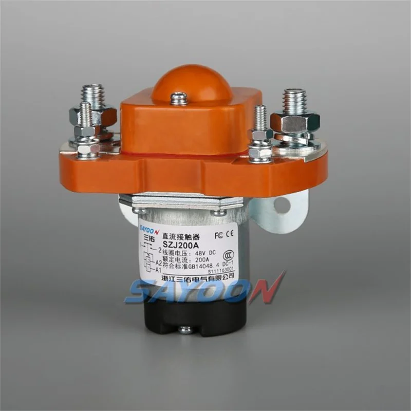
Las familias de productos Sayoon ofrecen diferentes clases de corriente, disposiciones de contactos, estilos de envolvente y opciones de bobina. El enlace SZJ200A normally open DC contactor es un ejemplo de producto relevante, no una aprobación automática para cada condición descrita aquí. Envíe el circuito real, el ciclo de trabajo, el entorno, la envolvente mecánica, las interfaces de cable y las pruebas requeridas con la consulta. La revisión de ingeniería debe confirmar el código de pedido completo y el plano antes de que se entreguen las muestras o las piezas de producción.
Para un proceso de comparación más amplio, utilice el Guía de selección de contactores de CC, el flujo de trabajo de prueba segura de contactores, y el cubo guía de voltaje de bobina. Estas páginas abordan decisiones adyacentes sin reemplazar la única pregunta respondida en este artículo.
Video educativo
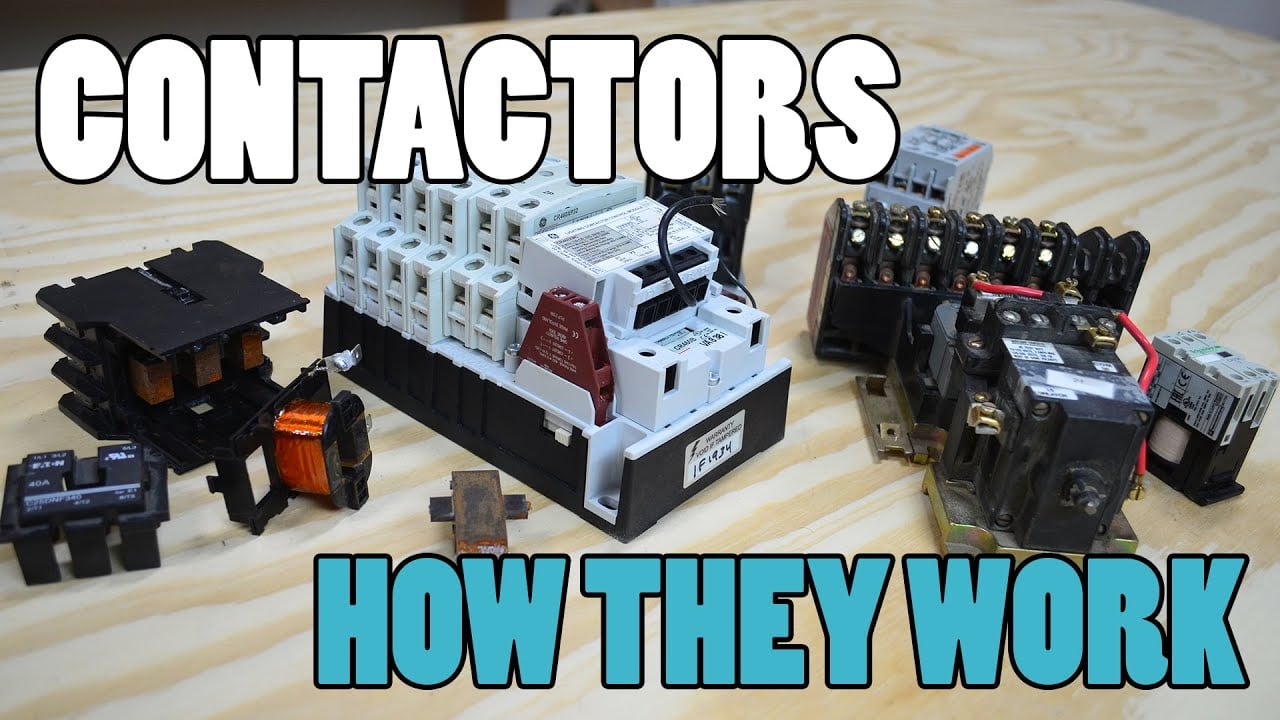
Qué es un contactor y cómo funciona, por Electrician U, ofrece una introducción visual relacionada con esta reseña. El procedimiento escrito anterior sigue siendo la guía de control.
Preguntas frecuentes
Is continuous duty always more demanding?
It is often more demanding thermally, while frequent intermittent switching can be more demanding for contact wear.
Does duty cycle equal starts per hour?
No. Starts per hour is one part of the switching profile; on-time and cooling time also matter.
Can a contactor be left energized overnight?
Only if the exact coil and installation are approved for the resulting continuous service and temperature.
Does an economizer change duty capability?
It can reduce hold power, but main-contact heating and application limits still require review.
What belongs in an RFQ?
Provide timing, current waveform, load type, voltage, ambient, enclosure, operations per hour, life target, and abnormal conditions.
Lista de verificación final
Antes de la liberación, confirme el número de pieza exacto, la revisión del plano, las funciones de la bobina y de los terminales principales, la forma de onda de la carga, la protección, el entorno, la instalación, el método de medición, los criterios de aceptación y el revisor. Compruebe que la prueba no omitió un enclavamiento ni creó una condición fuera de la clasificación del dispositivo. Si el candidato es un reemplazo, compare las interfaces y el comportamiento campo por campo; la similitud de tamaño o de corriente nominal no es prueba de equivalencia.
IEC 60947-4-1 es una referencia de normas relevante para contactores electromecánicos y arrancadores de motor. Utilice siempre la edición adoptada por el proyecto y obtenga los requisitos normativos completos a través del proceso de normalización responsable.





