A DC contactor vs battery disconnect switch comparison starts with the required action. A contactor allows a control circuit to command power switching. A manual battery switch provides local operation through its actuator. Their current ratings, switching duties, off-state functions, and fault behavior can differ substantially. Neither a remote command nor a red handle proves that a device provides qualified maintenance isolation. Select each function from the exact device documentation and the complete battery circuit.
This guide covers equipment design and purchasing. It does not provide a universal positive-terminal or negative-terminal installation rule, and it is not a live battery wiring procedure.
List the operating states that need a disconnect
Separate routine startup, normal shutdown, unattended fault response, maintenance, transport, storage, and emergency action. A device that works well for one state may not meet another state’s requirements. Identify who or what initiates each action: an operator, a battery controller, a machine controller, a protective device, or an approved service procedure.
Draw the boundary between the battery and the loads. Include chargers, converters, parallel batteries, always-on branches, monitoring connections, and stored load-side energy. A switch in one main conductor cannot be assumed to disconnect every path. Record the electrical state that is expected after each device opens.
Determine whether the required function is switching under load, disconnecting after another device has stopped current, preventing unintended reconnection, or establishing a service boundary. These distinctions should appear in the specification and test matrix rather than being inferred from the word disconnect.
Remote control and local operation serve different needs
A contactor can respond to a controller without an operator standing at the battery. That makes it useful for automated sequences, but the complete driver, supply, wiring, suppression, and supervision are part of the function. A controller command is not proof that the main contacts moved or that current stopped.
A manual battery switch may provide an accessible local action and a visible actuator position. Review whether that position has the documented relationship to the main contacts required by the application. Check accessibility, labeling, environmental protection, and the permitted operating duty. Do not assume every manual switch can interrupt the same load.
Some systems require both a routine remotely controlled function and a separate service arrangement. Other systems can meet their requirements with fewer devices. Add hardware only after the assigned functions, dependencies, failure responses, and verification methods are clear.
Switching rating and isolation function are separate
Carry current describes a conducting condition under stated circumstances. Making or breaking current is a different duty. For DC equipment, request the voltage, current, circuit characteristics, current direction where relevant, and permitted repetition for the assigned switching events. Do not transfer an AC switching capability to a DC battery circuit.
The standard summary for IEC 60947-3 distinguishes switches, disconnectors, switch-disconnectors, and related units within its scope. Use the exact product classification and applicable evidence when assigning an isolation function. A marketing term such as battery switch does not resolve that classification.
A contactor’s normally open description also does not automatically establish a service isolation function. Check construction, insulation evidence, feedback, failure behavior, and the complete approved procedure. Where the design calls for a lockable or independently verified service boundary, specify that requirement explicitly.
A function-based comparison table
| Requirement | Contactor questions | Manual switch questions |
|---|---|---|
| Automated normal stop | Does the command and feedback sequence match the load? | Is an operator action acceptable for this function? |
| Opening under load | What is the documented DC break duty? | What load-switching duty is documented? |
| Loss of control supply | What happens to the coil and remaining current? | What state remains without an operator action? |
| Service access | How is the required safe boundary verified? | Is the device’s isolation and locking function documented? |
| Unintended reconnection | How are control faults and restart commands addressed? | How are access, locking, and operator control addressed? |
| Instalación | Check terminals, coil harness, mounting, and protection | Check terminals, actuator clearance, mounting, and protection |
This table compares evidence to collect, not guaranteed capabilities. Populate it using the selected device, installation, operating states, and applicable equipment requirements.
Do not choose the conductor from a universal rule
Positive-side and negative-side arrangements must be assessed against the actual circuit, grounding, protective devices, chassis relationships, and applicable requirements. A convenient access point is not enough to determine a safe boundary. Multiple sources or grounded equipment can leave paths that a simple two-wire sketch does not show.
Describe which conductors must be separated and which measurements verify the result. Include chargers and external supplies during the review. Do not assume that removing a battery connection discharges a converter input capacitor or prevents backfeed through another branch.
Use qualified design and service personnel for the applicable system. This article deliberately does not prescribe a live connection sequence, a polarity choice, or an improvised test. Those decisions require the approved drawing and equipment procedure.
Precharge, inductive loads, and operating sequence
A downstream capacitor can produce a demanding closing event. Define the initial voltage difference and the approved charging arrangement. If a precharge sequence is used, record its completion condition, timeout response, and behavior when the main device fails to close or remains conducting.
For a manual switch, determine whether the operator is allowed to close directly onto the load under all permitted conditions. Labels and instructions must match the documented duty. A design that requires current reduction before manual operation should make that sequence explicit and assess foreseeable misuse.
Inductive loads require review of the energy released when current changes. The contactor or switch must be considered with the load, wiring, suppression, and protection. A controller stop request is useful only if the actual electrical result meets the approved sequence before the switching device operates.
Control supply, diagnostics, and failure response
A contactor coil must pick up, remain stable, and release appropriately over the control-supply envelope. Record cable losses, startup dips, charging conditions, suppression option, and driver behavior. Distinguish coil supply from the battery’s main-circuit voltage.
Define the response when an opening or closing command does not produce the expected state. Auxiliary indication and electrical measurements may have different diagnostic roles. The required supervision must detect the relevant failures without implying that one indicator proves the entire battery assembly safe.
For a manual switch, consider damaged contacts, a seized actuator, misleading position indication, inaccessible operation, and unauthorized reconnection. For both technologies, assign the response to a failed-conducting path and a failed-open path. Do not assume the most convenient failure state.
Maintenance and retained energy
A safe access procedure addresses every relevant energy source, stored energy, unintended reconnection, and verification step. A device name or actuator color cannot replace that procedure. U.S. workplace requirements in 29 CFR 1910.147 provide an authoritative reference where applicable; the equipment and jurisdiction determine the complete requirements.
For electric vehicles, consult the specific manufacturer service and emergency information. The DOE electric-vehicle maintenance and safety guidance discusses vehicle-specific resources and battery isolation methods. Do not substitute a general battery-switch article for those instructions.
Maintenance planning should also define inspection criteria, replacement triggers, approved spare parts, and the information retained after an abnormal event. Preserve the exact device ordering code and drawing revision so the installed function can be traced.
Verification and purchasing checklist
Keep an explicit list of circuits intentionally left connected for monitoring or other approved functions. Give those branches their own protection and service treatment. An operator should not have to infer the residual-energy boundary from the position of the main actuator or from a generic battery-off label.
Test the production-intent assembly at the permitted supply and temperature boundaries. Include normal operation, start, stop, control-power loss, defined abnormal conditions, and relevant operator actions. Record current, device voltage, coil or actuator behavior, feedback, joint temperature, and protection response.
Verify accessibility, marking, mounting support, conductor loading, terminal assembly, and the required prevention of unintended reconnection. Establish pass criteria before testing. Hazardous load interruption and fault tests require an approved qualified test arrangement.
Send the circuit drawing and state table with the RFQ. Include voltage and current envelopes, carry and switching duty, control or actuator requirements, feedback, protection, installation, environmental conditions, service function, and qualification evidence. Compare installed functional solutions rather than the prices of bare components.
Related documents and contactor fundamentals
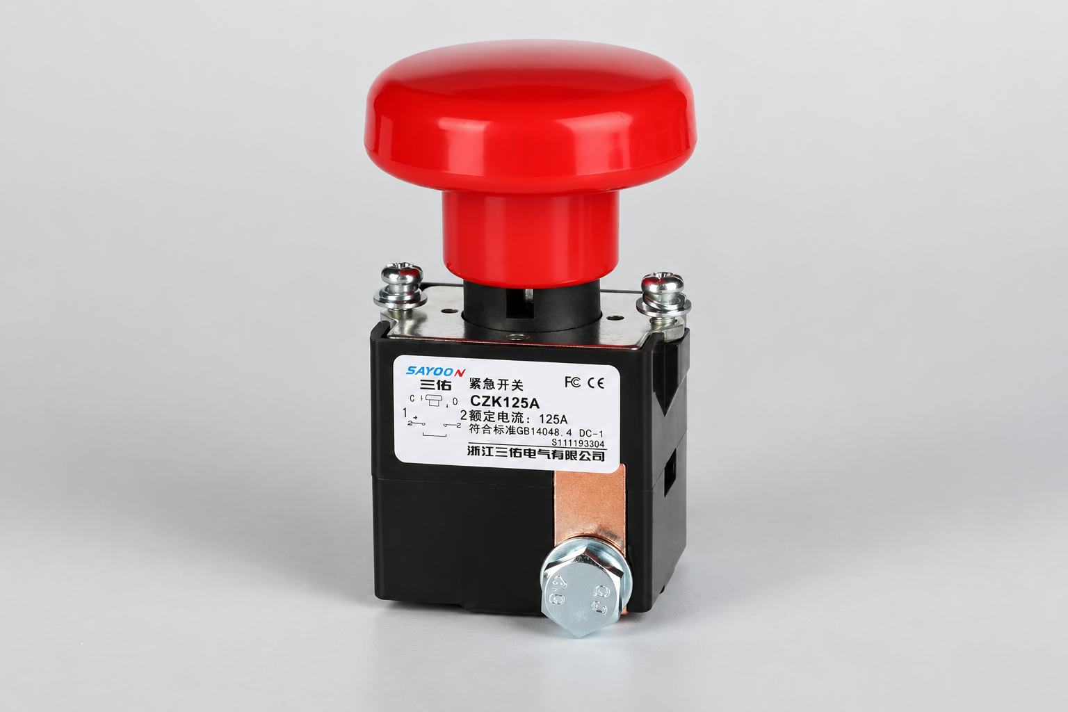
El CZK125A product page illustrates a manual switch for a document request; confirm the exact approved function before selection. For the remotely controlled alternative, review the contactor specification guide, coil control guide, y electrical life guide.
The Electrician U video below explains contactor operation. It is educational background, not a battery wiring or isolation procedure.

Preserve the tested configuration as part of the acceptance record. Changes to the device option, driver, protective element, terminal arrangement, mounting, or operating cycle need an assessment of whether the original evidence remains applicable. Keep unresolved differences visible in the approval record rather than treating a matching product name as an automatic release.
Preguntas frecuentes
Can every manual battery switch open under load?
No. Verify the exact documented DC switching duty and permitted operating sequence.
Does a contactor provide automatic maintenance isolation?
No. Assess the device function and the complete approved isolation and verification procedure.
Should the switch always go in the negative conductor?
No universal rule applies. Review the actual circuit, grounding, protection, and applicable requirements.
When might both devices be justified?
When routine remote switching and a separate qualified local or service function are required and the combined architecture is verified.





