A 900V DC contactor is suitable only when its documented main-circuit ratings cover the actual equipment voltage and switching duty. The number in a listing can be a maximum operating or switching limit, rather than a nominal system recommendation. Keep that limit separate from coil voltage, insulation test voltage and carry current. For a high-voltage battery or converter, verify the upper bus boundary, voltage across the open device, direction of interruption, fault coordination and installation conditions before approving a candidate.
This guide concentrates on specification review at a voltage boundary. Online descriptions often mix several ratings into one line. A buyer needs to determine exactly what 900V means, which circuit conditions qualify it, and what evidence is still missing from the replacement or new-design decision.
Turn the voltage headline into a defined requirement
Write the permitted main-circuit voltage range, highest normal operating value, applicable transient conditions and expected voltage across the contactor in every open state. These fields describe the equipment. Then ask the supplier for the corresponding operating and switching limits of the exact device.
A nominal battery label does not provide the maximum charging voltage. Likewise, a converter’s normal bus setpoint does not describe every energy-recovery event. Confirm both from the equipment documentation. If the proposed contactor’s limit is lower than the required operating boundary, select another supported variant rather than assuming unused current capacity compensates.
Do not interpret a one-time insulation withstand test as permission to operate or interrupt at that test voltage. A test can address insulation integrity under its stated conditions, while switching involves arc behavior and load energy. Ask which field each quoted voltage describes and retain the answer in the specification.
Check source combinations across an open device
Draw all sources, including charger, battery strings, converter capacitors and a connected test or service supply where applicable. The potential difference across an open contactor depends on these states. A contactor placed between two independently energized nodes deserves a different review from a simple source-to-load disconnect.
Consider normal switching order, one contactor failing to change state, and a source remaining available during shutdown. Do not assume two series contactors each see half the voltage. Equal sharing needs a justified circuit arrangement; stray capacitance or leakage is not a dependable design basis.
Record what each voltage measurement means. An auxiliary contact reports a mechanical signal under its documented arrangement; it does not measure the potential across the main gap. Use appropriate voltage sensing and diagnostic design when the equipment decision requires that information.
Organize insulation and switching questions
| Review field | Equipment information | Evidence to request |
|---|---|---|
| Operating voltage | Highest main-circuit voltage and relevant states | Explicit operating range for the ordering code |
| Gap voltage | All sources across the open main path | Supported voltage across each device in the actual arrangement |
| Isolamiento | Power-to-control and mounting environment | Installation drawing and relevant insulation evidence |
| Breaking duty | DC current, direction and circuit characteristics | Qualified interruption limits and allowed repetition |
| Circuito de control | Coil supply and feedback dependencies | Coil envelope, suppression and feedback documentation |
| Qualification | Supplier tests versus installed checks | Traceable evidence for each separate requirement |
These review fields separate different evidence types. A passing insulation result cannot close an unresolved interruption question, and a breaking test cannot authorize arbitrary mounting clearances. The supplier and equipment designer should identify who owns each limit and how it is verified.
Assess insulation in the installed assembly
Review the insulation between main terminals, each power terminal and control circuits, and each relevant terminal and accessible mounting structure. Confirm the manufacturer’s installation requirements, barriers and permitted orientation. Creepage and clearance decisions belong to the complete equipment design and applicable requirements.
Do not calculate one universal clearance from 900V alone. Pollution conditions, material characteristics, overvoltage environment, altitude and equipment classification can affect the assessment. Ask for the documented assumptions and approved drawing instead of copying a spacing number from an unrelated device.
El IEC 60947-4-1 record identifies the contactor standard and its scope. It does not certify the illustrated product or define every installation detail. Evaluate the selected model together with the rules applicable to the finished equipment.
Require actual DC breaking evidence
Specify the current, voltage, circuit characteristics and direction when the main path opens. DC interruption cannot be approved by transferring an AC rating with similar numbers. Ask for supported load duty and the allowed operation frequency at the relevant conditions.
Separate normal commanded opening from opening after a converter fault or protective trigger. A device permitted to disconnect a nearly unloaded bus may not be assigned to interrupt a sustained abnormal current. Define the protection sequence and assess what happens if current reduction does not occur.
For directional arc control, retain terminal orientation and switching-direction instructions. Battery charging and discharge can reverse current. Document whether opening can occur during either state, rather than calling the contactor bidirectional because closed contacts conduct both ways.
Review the making event and restart logic
When connecting a converter capacitor, provide capacitance, initial voltage difference, the precharge path and the criteria for main closure. The educational explanation of capacitance describes stored charge; product-specific making evidence and circuit analysis are still needed.
A failed or interrupted precharge cycle can leave a partial charge. Define how restart detects that condition, what completion signal it uses and when retries stop. Avoid treating a successful first startup as proof of correct behavior after every control-power interruption.
Include an implausible feedback state in the logic review. If a main path is already closed when the controller believes it is open, the expected precharge circuit may not describe the actual connection. The equipment’s diagnostics and protection must address that state with suitable verification.
Check thermal and control limits independently
Provide continuous current, peak duration, switching repetition and enclosure temperature. The heat result depends on installed conductors and connections as well as the internal contacts. A high voltage capability does not imply a particular continuous current rating under every mounting condition.
Specify coil supply at the device, including pickup demand, holding demand and allowed variation. Confirm internal electronics, economizer, suppression and polarity. The controller’s output and fault response must be suitable for the actual ordered variant, not merely a generic relay symbol.
Record release behavior where it matters to another device’s timing. A coil command and a confirmed main-path state are different observations. Test the intended sequence within the approved control-supply envelope and retain the result.
Plan qualification without overstating a bench check
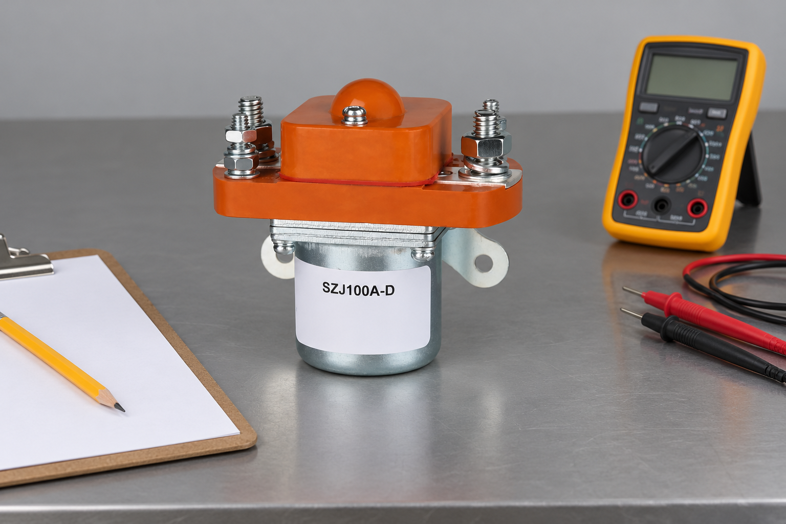
An isolated continuity test can help identify contact states. It does not prove interruption capability, dielectric suitability or fault withstand. Qualification of high-energy switching requires appropriate equipment, controlled conditions and personnel competent for the work. Define which evidence comes from the supplier and which installed checks remain with the equipment builder.
For covered workplace servicing, OSHA 1910.333 addresses de-energization, lockout and verification. A controller stop signal or a contactor click is not sufficient evidence that accessible circuits are de-energized. The procedure must account for capacitors and alternate sources.
Build an RFQ that exposes unsupported assumptions
Supply a circuit-state drawing, operating voltage range, required switching duty, current directions, protective devices, coil envelope and installation environment. Ask the supplier to identify the exact supported ordering code and any limits that remain unresolved. Require written clarification if a listing uses 900V without describing the rating field.
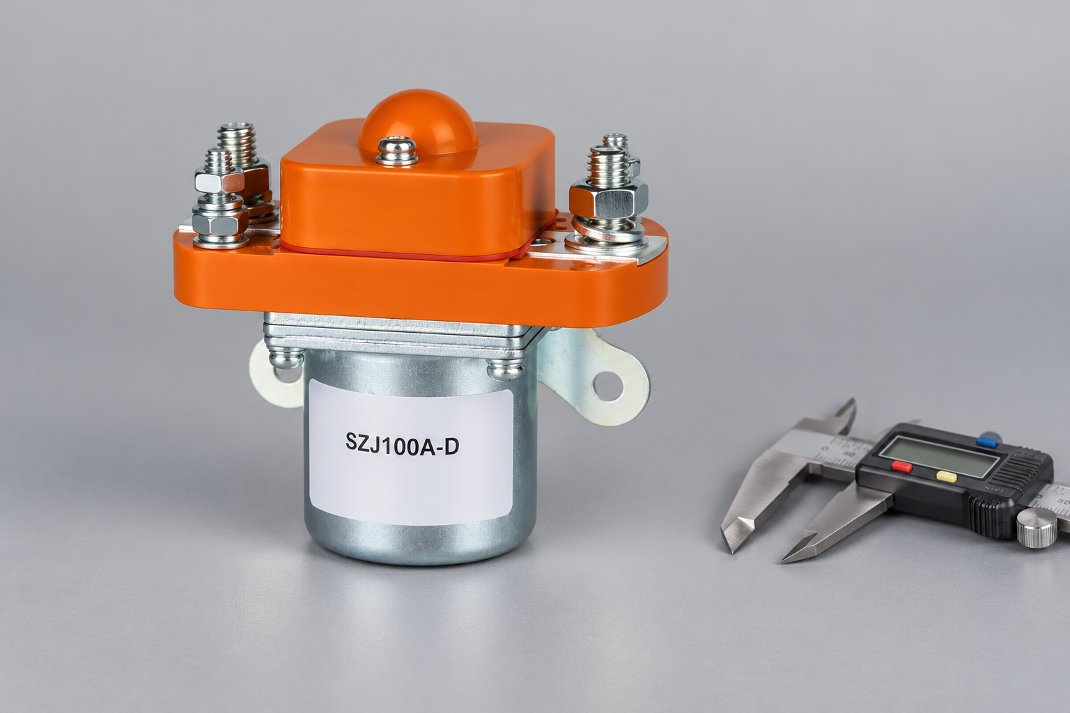
Review the SZJ100A-D Normally Open DC Contactor product page for an external construction reference. This conventional construction example is not a qualified candidate for the article’s stated duty; obtain an appropriately rated variant and product-specific evidence from Sayoon. The pictured contactor demonstrates external construction and does not establish 900V qualification. Use the OEM specification checklist to organize the evidence. For focused supporting checks, review insulation coordination, y feedback plausibility checks. Retain approved limits, drawing revisions and validation records with the purchasing file so a subsequent replacement cannot be accepted from appearance alone.
Resolve conflicting catalog descriptions before ordering
If a distributor listing, product label and supplier drawing use different voltage descriptions, request a written explanation tied to the ordering code. Record which document controls selection and whether the listing refers to operating voltage, maximum switching voltage or insulation testing. Do not average incompatible claims or choose the largest number because it is more convenient.
Retain a copy of the approved revision. A later catalog update should prompt comparison with the existing qualification, particularly when an internal design or control variant changes without an obvious housing change. Buyers need a traceable application decision rather than a screenshot containing an unexplained 900V headline.
Watch the basic contactor operating principle
Electrician U explains the electromagnetic contactor mechanism in this educational video. It supports the operating principle only; it does not demonstrate the selected model’s DC ratings, qualify this application or replace product documentation.

Watch the Electrician U contactor explanation on YouTube.
Preguntas frecuentes
Is a 900V insulation test the same as a 900V operating rating?
No. Insulation testing, operating voltage and switching ratings describe different conditions. Check the documented meaning of each value.
Can two series contactors each be rated for half the bus voltage?
Do not assume that arrangement is valid. Evaluate voltage across each device in every relevant state and use verified rating and insulation evidence.
Can 900V be applied to the coil?
Only if the exact coil documentation explicitly specifies it. The power-circuit voltage and control-supply voltage are separate requirements.
Does a continuity test prove high-voltage switching suitability?
No. It checks the measured contact state under that test condition. It does not establish DC breaking capability, insulation qualification or fault withstand.





