Respuesta rápida: A BESS bidirectional contactor must carry charging and discharging current, but “bidirectional” also needs a precise switching definition. Confirm whether the device may make or break current in both directions, at the full DC voltage and actual circuit inductance. Then verify continuous thermal duty, precharge, fault coordination, coil control, auxiliary feedback, insulation, environment, and electrical endurance for every operating quadrant.
Esta guía convierte el tema en un flujo de trabajo revisable para el diseño, puesta en marcha y adquisición de BESS. Utiliza como referencia visual al propio contactor Sayoon, manteniendo todos los valores, órdenes de secuencia y decisiones de seguridad vinculados al sistema final y a la documentación actual del fabricante.
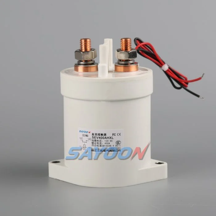
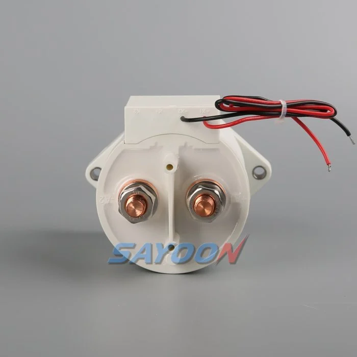
Mapa de decisiones de ingeniería
| Estado del sistema | Condición eléctrica esperada | Foco en el diseño |
|---|---|---|
| Charge | PCS to battery | Continuous heating, charging limits, reverse current |
| Discharge | Battery to PCS | Peak current, bus sag, terminal temperature |
| Normal opening | Current reduced before opening | Residual current and DC arc direction |
| Emergency opening | Abnormal current in either direction | Qualified break duty and fuse coordination |
Referencia y ámbito del producto
El SEV400AHXL sealed high-voltage DC contactor es un ejemplo relevante de una familia de productos reales. Verifique Guías de contacto de alto voltaje de tipo DC y Guía de selección de contactores de CC para el flujo de trabajo más amplio. Una coincidencia visual o un valor nominal de corriente no avalan un modelo para un BESS. Confirma la tensión, el corriente a transportar, el régimen de carga y desconexión, la polaridad, la aislación, la temperatura, el entorno, la vida útil, el montaje, el accionador y la protección.
Define what bidirectional means
Current can flow toward the battery during charging and away from it during discharge. Carrying current in both directions is not the same as interrupting current in both directions. Internal magnetic arc control can make DC breaking performance polarity-sensitive even when the main terminals look symmetrical. Ask for explicit make and break data for each required direction, voltage, current, load type, and time constant.
Create an operating-state table that lists current direction at closure, during steady carry, and at opening. Include regeneration from the converter, charging from the grid, black-start behavior, DC-coupled generation, and maintenance tests. A state with nominally zero current should still specify a residual-current limit and how the controller verifies it.
Use maximum system voltage
Select against maximum charged battery voltage and defined transients, not only the nominal BESS label. The PCS can impose voltage during startup, shutdown, or a fault. Confirm which terminal may be positive in each state and whether the approved rating changes with polarity. Do not use an AC rating to infer DC interruption capability.
Insulation review covers dielectric strength, clearance, creepage, sealing, pollution, altitude, enclosure geometry, and distances to grounded metal. The completed assembly must be assessed because nearby busbars, sensors, and barriers change the effective insulation path.
Separate carry, make, and break duties
Continuous current drives I-squared-R heating. Make current depends on voltage difference, DC-link capacitance, precharge success, and circuit resistance. Break duty depends on current, voltage, inductance, polarity, contact opening, and protection action. A headline ampere rating does not combine these conditions. Use measured waveforms from charge and discharge operation.
List normal openings separately from emergency interruptions. Normal control should reduce PCS current before opening when the safety concept allows. Emergency duty may be limited to a small number of events, but it must still be supported by evidence and coordinated with the fuse or pyrofuse.
Check thermal performance in both modes
Charging and discharging may have different duration, RMS current, enclosure temperature, and cooling. Fast charging can create a long high-current period after a hot discharge. Model the full daily profile and validate it on production-intent busbars. Measure terminal and body temperatures after thermal stabilization.
Contact resistance, joint resistance, terminal torque, conductor size, surface condition, and neighboring components influence temperature. Use consistent four-wire voltage-drop points where practical. A device can meet average current yet exceed temperature limits during a stacked sequence of charge and discharge events.
Coordinate precharge and polarity
Precharge should reduce the voltage across the main contacts before closure. In a bidirectional system, either the battery or PCS side may be energized first, so the branch topology and resistor stress must be checked for both directions. Confirm blocking devices, sensing, and control logic prevent an unintended discharge through the precharge branch.
Authorize closure from measured voltage difference and stable polarity. Define the response to reversed sensor leads, a welded precharge contactor, open resistor, failed bus sensor, or externally energized PCS. Repeated failed attempts are counted in the duty profile.
Design feedback and fault logic
Auxiliary feedback reports mechanism position within its limits. Correlate it with command, coil current, pack-side voltage, bus-side voltage, and PCS current. If the commanded-open device still shows current or equalized voltage, investigate a weld, back-feed, sensor error, or parallel path. If commanded closed but current cannot flow, check the fuse, busbar, connection, and main path.
Store the first mismatch with direction, voltage, current, temperature, and timing. Avoid automatic retries when the system cannot prove an open state. Fault recovery should require controlled discharge and an explicit safe-state decision.
Validate interruption and protection
Calculate prospective fault current from battery strings and every parallel source. The contactor may only need to withstand current until the fuse clears, or it may be required to interrupt a defined current. These are different duties. Confirm the exact coordination, including current direction and available energy.
Test representative switching on production-intent hardware with the approved protection. Inspect contact resistance, timing, insulation, temperature, and physical condition before and after endurance blocks. A test at lower voltage or favorable polarity does not establish performance in the opposite quadrant.
Build the RFQ around waveforms
Provide minimum, nominal, maximum, and transient voltage; charge and discharge current traces; current at make and break; DC-link capacitance; circuit inductance; precharge; fault current; protection clearing; temperature; enclosure; altitude; vibration; mounting; busbars; coil voltage; driver; suppression; feedback; life; and required standards.
Request a drawing and product-specific evidence for both current directions. The SEV400AHXL shown here is a real product reference, not automatic approval for the application. Final selection requires the exact ordering code and verified duty.
Control changes through service life
Recheck the validated envelope when the battery configuration, PCS firmware, busbar, fuse, cooling, sensor, coil option, driver suppression, or daily operating profile changes. The contactor may look unchanged while make current, opening duty, temperature, release time, or insulation stress has changed. Compare revisions against a controlled baseline and repeat the affected calculations and tests.
During maintenance, inspect terminals, barriers, conductors, heat evidence, contamination, mounting, control wiring, and stored faults. Trend voltage drop and temperature only at comparable current and measurement points. After replacing a contactor, fuse, sensor, or controller, repeat the approved precharge, close, load, open, discharge, feedback, and restart-inhibit sequence before returning the rack to service.
Control de la seguridad y la evidencia
Trate la batería, los condensadores comunes, los convertidores, los racks paralelos, los suministros auxiliares y el equipo de prueba como fuentes de energía peligrosas hasta que una persona autorizada haya aplicado el procedimiento de aislamiento del sitio y verifique el estado requerido con instrumentos de medición homologados. No debe conectar pines de retroalimentación, forzar una bobina, deshabilitar los interbloques de alta tensión ni abrir un dispositivo fuera de su ámbito de funcionamiento homologado. Un BESS puede seguir estando alimentado desde una dirección que no queda clara en un esquema simplificado.
Generar límites de aceptación basados en los datos exactos del producto, los requisitos del sistema aprobados y las pruebas representativas. Registre el código completo de pedido, la revisión del dibujo, la opción de bobina, el mapa de terminales, la disposición de los conductores, las ubicaciones de los instrumentos, la calibración, la temperatura, la versión del software, las formas de onda sin procesar, los criterios de aprobación/rechazo, las desviaciones y los revisores. Separe los datos medidos de las interpretaciones. Cuando faltan pruebas, registre una acción abierta en lugar de introducir un valor estándar.
Guías de ingeniería relacionadas
Utiliza el Guía de dimensionamiento del resistor de carga preinstalada, Guía de plausibilidad de los comentarios del contactor, Guía de resistencia a los cortocircuitos, y Guía de coordinación de aislamiento como comprobaciones complementarias. Estas páginas cubren diferentes decisiones y deberían aplicarse al mismo límite de sistema aprobado.
Video educativo
A Look At High-Voltage EV Contactor Technology by CHARGED Electric Vehicles Magazine provides visual background on contactor operation and high-voltage switching. It does not replace the written design requirements or the product-specific validation.
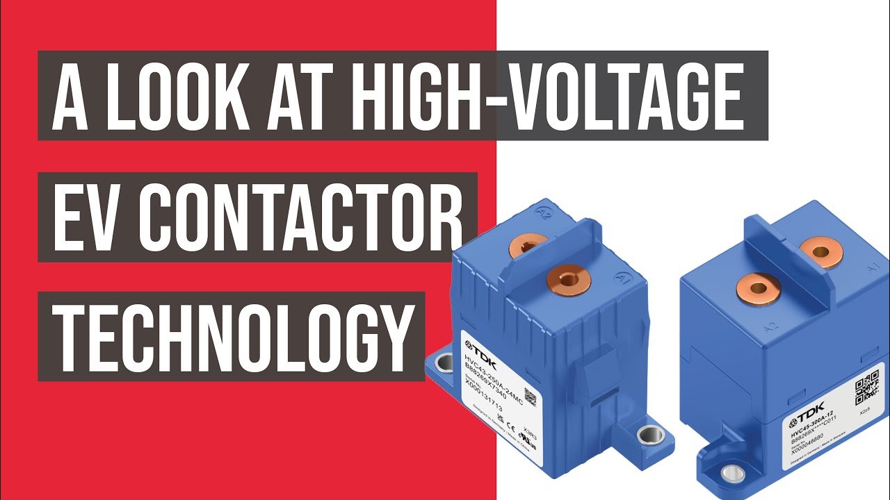
Mira el video educativo en YouTube.
Preguntas frecuentes
What is the first rule for bess bidirectional contactor?
Defina los límites del circuito y cada fuente que pueda generarlo, luego verifique la exactitud del dispositivo en función de las formas de onda de voltaje y corriente medidas.
¿Puede la retroalimentación auxiliar demostrar que los contactos principales están abiertos?
No. Relacione el estado auxiliar con la tensión del bus, la corriente de la cuerda, la corriente de la bobina, el tiempo de funcionamiento y todos los posibles caminos de retroalimentación.
¿Debería un contactor reemplazar un fusible de cadena?
No. Un contactor proporciona un conmutador controlado, mientras que un fusible proporciona protección contra el flujo de corriente defectuoso. Sus funciones de resistencia y desconexión deben coordinarse.
¿Qué datos deben incluirse en la solicitud de presupuesto para el contacto de un BESS?
Incluya el rango de voltaje, las formas de onda de corriente, el modo de funcionamiento de corte y conexión, la dirección de la corriente, la carga previa, el corriente de fallo, la protección, la temperatura, el montaje, el control de bobina, el retroalimento y el objetivo de vida útil.
Referencias autorizadas
- OSHA 1910.147 — Control de la energía peligrosa
- OSHA 1910.333 — prácticas de trabajo eléctrico
- IEC 60947-4-1 — contactores y arrancadores de motor
- Departamento de Energía de los Estados Unidos — almacenamiento de energía
Utilice las ediciones y requisitos adoptados por el proyecto. Los estándares y los datos del producto pueden cambiar, por lo que el equipo de ingeniería responsable debe confirmar el diseño final.





