A contactor coil temperature rise test asks how much hotter the coil system becomes than its surrounding air under a defined voltage, duty, mounting and load condition. A warm case alone is not a failure verdict. Equally, a coil that works once at room temperature has not passed a continuous-duty heat assessment. For a DC contactor, separate heat generated by the coil and its driver from heat conducted from main contacts, busbars, terminals and the enclosure. Use the exact product’s published coil and ambient limits as the acceptance basis; record the method and conditions so another engineer can reproduce the result. Never borrow an absolute temperature limit from a different model.
Define the test boundary before touching the hardware
Identify the full contactor order code, coil-voltage option, auxiliary contacts, built-in suppression and any economizer. A 24 V DC marking on a photograph is not sufficient proof of the ordered item’s duty or thermal limit. Obtain the model-specific drawing and permissible continuous energization, ambient range, operating voltage band, mounting orientation and applicable test instructions. Ask whether the manufacturer specifies a coil-winding temperature-rise limit, a case-surface limit, or another criterion. These are different measurements. A surface thermometer cannot directly establish an internal winding temperature unless a validated correlation exists.
Define two separate scenarios if the application needs them. A coil-only test energizes the control coil while the main circuit carries no load, making it easier to isolate control-circuit heating. A combined-duty test operates the main circuit at its specified current and switching profile, capturing additional heat transferred through contacts, conductors and enclosure air. Do not subtract the coil-only result from the combined result and call the difference “contact heating” without a thermal model: heat-transfer paths are coupled. Record both conditions independently with the same ambient and mounting details.
Manufacturer examples show why duty and construction matter. A Schneider Electric 24 V DC coil product entry publishes its own hold power, ambient and control-voltage limits. Those figures illustrate the kinds of parameters to request, not an acceptance target for Sayoon. Schneider’s low-control-voltage guidance warns that incomplete closing or chatter can contribute to damage. That warning reinforces the need to test at the actual coil terminals, including the low-voltage pickup corner, rather than simply running an overvoltage heat soak.
Choose measurements that answer distinct questions
Ambient temperature is measured near the installed contactor but away from a direct heater plume, forced-air jet or a surface that biases the sensor. Note the sensor location and airflow, because “25 °C room temperature” does not mean the enclosed coil sees 25 °C. Measure an accessible housing point and, if permitted by the product and test procedure, identified terminal and coil-adjacent points with instruments suitable for the voltage environment. Use repeatable attachment, insulation and calibration. An infrared camera can reveal patterns, but emissivity and reflections make a shiny metal stud particularly unreliable as an absolute temperature measurement without correction.
Capture coil-terminal voltage and current at the same time as the temperatures. Current can change as the coil warms, and an economizer can switch to a lower hold mode. If the coil uses built-in electronics, the relationship between terminal voltage and winding power need not be a simple V²/R rule. Note whether the test is an initial pickup, continuous hold, repetitive cycling or a duty with long off periods. A coil that is thermally acceptable for a short pulsed operation is not thereby approved for uninterrupted energization. A coil-only hold test also cannot establish the power contacts’ load-current temperature rise.
Temperature rise is commonly written ΔT = measured component temperature − local ambient temperature at a defined condition. This subtraction is useful only when the component and ambient measurements refer to the same stabilized period and well-defined locations. If the air inside an enclosure rises over time, an outside-room ambient reading can falsely enlarge or hide the local rise. Record both ambient and enclosure air, and state which reference the product’s criterion requires. Log an actual time series rather than a single end-point photograph.
| Test phase | Control and main-circuit condition | Registro | Decision question |
|---|---|---|---|
| Baseline | De-energized, thermally settled | Local ambient, enclosure air, case and terminal temperatures | Is the starting state reproducible? |
| Pickup | Worst documented low supply; defined main-load state | Coil-terminal voltage, current, closure and feedback | Does it close fully without chatter? |
| Continuous hold | Specified high supply, rated control duty | Voltage, current, local ambient and temperature time series | Has the thermal response stabilized within exact limits? |
| Combined load | Specified main current and realistic switching duty | Terminal, housing and enclosure temperatures | Does adjacent power-circuit heat change the result? |
| Cooldown and repeat | Control off, prescribed restart interval | Release, cooldown profile, subsequent pickup | Is performance repeatable after heat soak? |
Set a credible thermal stabilization rule
Run long enough for the result required by the product’s test method, not for an arbitrary convenient hour. A large enclosure and busbar can take much longer to stabilize than a small isolated coil. Define the stabilization criterion before testing, using a manufacturer method or an approved laboratory protocol. Record temperatures at regular intervals and do not declare equilibrium while they are still rising materially. If the specified duty cycles the coil, reproduce the intended on/off pattern and switching frequency; continuous hold is a different exposure.
Test the relevant voltage corners separately. At the high sustained supply, electrical input and heat can increase; at the low supply, slow or incomplete pickup can create a different stress, depending on design. Avoid simplistic claims that undervoltage always makes a DC winding hotter in steady state: a plain resistive DC winding would draw less power at lower voltage, whereas an electronic drive or delayed mechanical closure changes the picture. The actual coil construction and measured waveforms govern the inference. ABB’s troubleshooting note discusses control-voltage disturbance and overheating risk in particular contactor designs; it should not be transposed into a universal Sayoon limit.
Include the intended mounting orientation and neighboring heat sources. A row of closely packed components can trap warm air differently from an isolated bench assembly. Terminal and cable size also influence heat flow out of the device; the exact installed conductor and torque specification matter. If a cooling fan is part of the application, record its airflow and failure-state expectation. A test with an open cabinet door may understate operating temperature inside a closed enclosure. Avoid changing several variables at once when isolating the cause of a surprising temperature reading.
Interpret unexpected hot spots without guessing
If a coil area warms faster than expected, first verify voltage at its terminals, current and energization time against the exact documentation. Check whether it has fully closed, whether the economizer is operating, and whether a suppressor or wiring error changes behavior. If a main terminal or busbar is the hot point while the coil is comparatively cool, investigate connection integrity, conductor specification and main-circuit duty under a separate approved diagnostic procedure. Do not loosen or touch a live terminal as a diagnostic shortcut. Thermal images can locate a region, but calibrated contact measurements and electrical data are needed to explain it.
Compare the temperature rise and absolute temperature to the product’s specified criteria as applicable. A 35 °C rise at a 20 °C ambient produces a different absolute surface temperature from the same rise at a 55 °C ambient. The governing acceptance criterion may be internal insulation class, specified terminal rise, external surface limit or application-specific enclosure limit. Do not substitute one for another. If no Sayoon limit is available for the exact item, label the result NEEDS_REVIEW and request product engineering confirmation; a visually reasonable temperature is not a formal pass.
Keep application safety separate from the thermal numbers. A contactor in a battery system may be connected to hazardous stored energy even while its coil supply is removed. Qualified personnel should isolate the main circuit, follow the site’s hazardous-energy procedure and use appropriately rated probes and thermal sensors. A feedback contact cannot alone prove isolation. Our Guía de prueba para contactores de corriente continua discusses electrical measurement boundaries; opening and closing time matters when heat is accompanied by slow motion or chatter.
Document a repeatable result and connect it to selection
A useful report includes the exact part number and coil option, product drawing revision, mounting and enclosure, conductor sizes and torque evidence, local and external ambient conditions, airflow, supply envelope, coil-terminal voltage and current traces, duty cycle, main load current, sensor locations and calibration, timestamped temperature traces, stabilization criterion and the model-specific acceptance source. Include photographs that clearly show sensor locations without pretending a standard product photo is a thermal result. State separately whether the coil-only and combined-load conditions passed their applicable criteria.
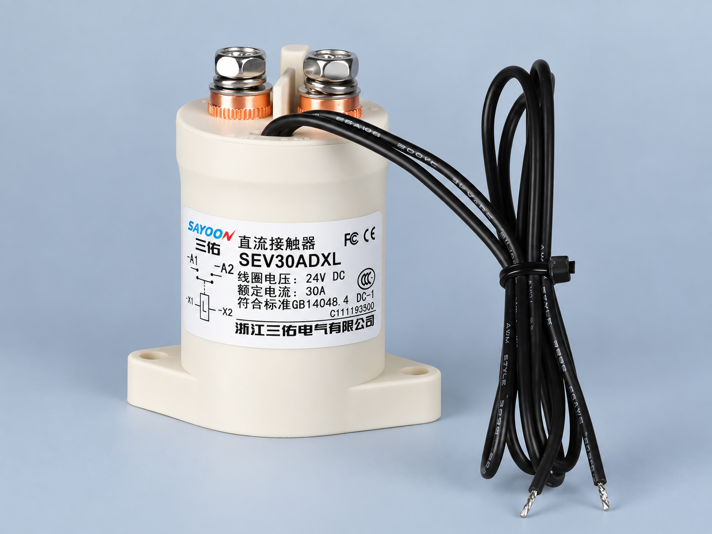
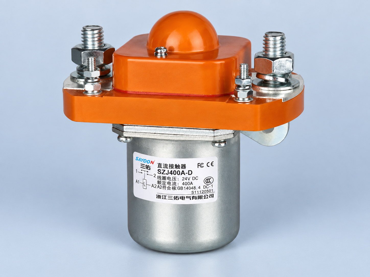
El Sayoon SEV150AD product page is the real featured product reference here. The body also shows the SEV30AD and a distinct SZJ construction, illustrating why one photo or generic temperature value must not be applied across families. Send the measured operating conditions and exact ordering code with your RFQ. For the upstream electrical input, read our coil power guide; for the overall device decision, read the Guía de selección de contactores de CC. These explain different questions and should not be conflated with a formal temperature-rise qualification.
Video: contactor basics before a thermal test
This independent training video demonstrates contactor construction and basic checks. It does not present a Sayoon temperature-rise test or replace a model-specific thermal criterion.
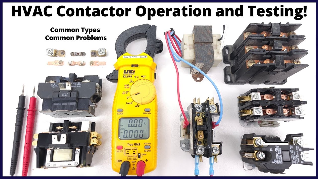
Watch the AC Service Tech overview on YouTube.
Preguntas frecuentes
Is a warm contactor coil automatically defective?
No. Judge the measured temperature rise and absolute temperature under a defined duty against the exact product’s stated criteria, with local ambient and test conditions recorded.
Can I use an infrared camera alone to pass the test?
Not reliably. Surface emissivity, reflections and the difference between case and internal winding temperature require an approved measurement method and calibrated evidence.
Should the main contacts carry current during the test?
Run separate coil-only and specified combined-load conditions if both matter. Main-circuit heating can influence the coil environment, so document each condition independently.
How long should a coil temperature rise test run?
Follow the exact product or approved test method and a predeclared stabilization criterion. A fixed arbitrary duration does not establish thermal equilibrium for every enclosure.





