Respuesta rápida: For an ev battery positive negative contactors design, specify each pole for the maximum battery voltage and prospective fault current, give the pack a controlled precharge path, verify auxiliary feedback independently, and define what happens when either device fails to open or close. A contactor is a component in a safety sequence; it is not a substitute for fuses, isolation monitoring, or a documented discharge circuit.
An EV battery pack normally uses separate positive and negative main contactors so the battery-management system can control both conductors instead of leaving one side permanently connected. The pair supports isolation, precharge, discharge, service, and fault handling. The correct design is about current direction, voltage, fault energy, coil behavior, feedback, and sequence—not simply installing two switches with the same ampere rating.
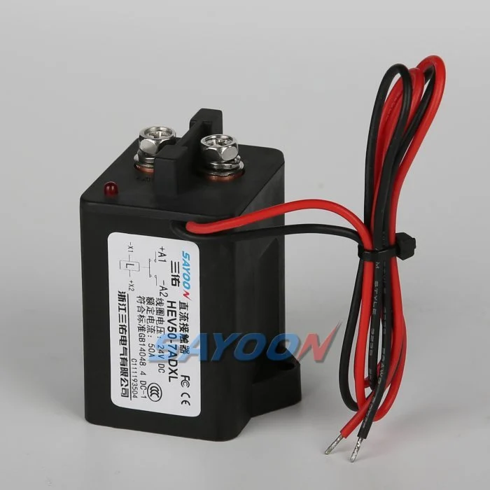
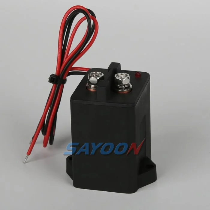
At-a-glance design map
| Element | What it does | Selection or diagnostic focus |
|---|---|---|
| Positive main | Connects or isolates the positive bus | Voltage, make/break current, insulation, thermal duty |
| Negative main | Completes pack isolation and controls return path | Same voltage class, bidirectional current, fault coordination |
| Precharge contactor | Limits DC-link inrush before the main pair closes | Resistor pulse energy, timing, current and weld risk |
| Retroalimentación auxiliar | Reports mechanism position to the BMS | Contact rating, debounce, plausibility and diagnostics |
Referencia y ámbito del producto
The HEV50 high-voltage sealed DC contactor shown in this article is a real Sayoon product reference. See the HEV50 high-voltage sealed DC contactor product page y las Gamma de contactores DC de alta tensión for the family context. The image does not replace a model-specific drawing review; voltage, coil, current, insulation, duty, and mounting must be confirmed for the application.
Why two main contactors are used
A traction battery is a floating high-voltage source. Opening only the positive conductor can leave the negative side connected to an inverter, charger, heater, or service interface. That may defeat the intended isolation boundary and can leave hazardous potential at parts of the harness. A positive and a negative main device let the BMS create a predictable open state and check the pack before enabling propulsion. The pair also allows the controller to detect asymmetric failures: one device can be commanded while the other remains open for a diagnostic test.
The pair should not be treated as interchangeable by default. Cable routing, busbar clearance, current-sensor placement, fusing, and the contactor coil return can differ. Some packs switch the negative path through a current sensor or shunt, while others place sensing elsewhere. The electrical drawing should show the exact current path and the state of every auxiliary contact.
Precharge is part of the contactor strategy
An inverter DC link often contains capacitors that look like a near-short circuit when empty. Closing a main contactor directly can create a high inrush pulse, contact erosion, or a weld. A precharge contactor and resistor charge the link in a controlled way before the main pair closes. The BMS should compare pack voltage with DC-link voltage rather than relying only on a fixed delay. A delay that works on a cold, empty bus can be wrong when capacitance, temperature, leakage, or charger state changes.
The precharge resistor has a pulse-energy and repeat-duty limit. Size it for the largest expected voltage difference and the longest permitted charge interval, then verify that the main contactor closes only after the measured ratio is inside the approved window. The Fluke explanation of inrush measurement is useful background for understanding why a short, high current pulse can damage a switching device even when the steady load is modest.
Ratings that matter in an EV pack
Read the contactor data sheet as a set of conditions. Continuous current depends on ambient temperature, mounting, conductor size, and duty cycle. Make current is different from continuous current; breaking a DC load is different again because the arc does not naturally pass through zero. Check the maximum working voltage, insulation withstand, creepage, clearance, polarity guidance, short-circuit coordination, and coil pull-in/hold behavior. A nominal “400 A” label is not enough to approve a 400 V or 800 V pack.
Regenerative charging can reverse current through the main path, so verify that the contactor is rated for the actual bidirectional operating envelope. If a device is only approved for making current in one direction or under a particular suppression network, document that restriction. Use the Sayoon high-voltage contactor range as a starting point, then send the battery voltage, peak current trace, enclosure temperature, and required life to engineering for a model-level confirmation.
Feedback, isolation and fault states
Auxiliary contacts indicate mechanism position, not necessarily a healthy low-resistance main path. The BMS should combine command state, auxiliary state, measured bus voltage, and isolation-monitor status. If the command is open but the bus remains energized, treat the event as a welded or externally back-fed path until proven otherwise. If the auxiliary says closed but the expected voltage does not arrive, treat it as stuck open, miswired, or mechanically incomplete.
Define a safe state for every mismatch. A failed positive device may require the negative device to remain open; a failed negative device may block precharge and service release. Avoid automatically retrying a suspected weld. Store the first fault, inhibit propulsion, and require a controlled discharge and service procedure. The test record should capture the pack state, measurement points, time stamps, and contactor identity.
Coil drive and thermal behavior
The coil supply must remain inside the approved pull-in and hold range during low-voltage battery conditions, cold start, and contactor switching transients. Economized coils can draw a short pull-in current and then a lower hold current; a generic diode, PWM driver, or high-side switch can change release time and diagnostic signatures. Place suppression and current sensing where the manufacturer expects it, and validate the control output with the real harness length.
Coil heating is part of pack thermal design. Three devices can be energized during precharge or charging, and repeated key cycles can accumulate heat even when the main current is zero. Measure pull-in time, hold current, dropout voltage, and release time at the lowest and highest supply conditions. The related PLC coil-control guide explains the same interface questions in a lower-voltage context.
Verification sequence before release
Start with a de-energized continuity and insulation check, then verify terminal identity against the drawing. With current limited, exercise the precharge sequence and record pack voltage, link voltage, coil current, auxiliary transitions, and time stamps. Repeat with the pack cold and warm and with the inverter in its real operating state. Check that an open command removes energy from both conductors and that the discharge path reaches its specified threshold.
Do not bypass the HVIL, service disconnect, fuse, or isolation monitor during a “quick” test. OSHA lockout and electrical-work practice requirements are a useful safety framework, but the pack manufacturer rules remain controlling. The safe contactor testing guide linked above provides a conservative workflow for instruments, isolation, and evidence.
How to specify the pair in an RFQ
Include nominal and maximum battery voltage, continuous and peak current, current direction, short-circuit source, precharge resistor value and pulse profile, coil voltage, suppression, auxiliary contact logic, enclosure temperature, vibration, altitude, sealing, terminal orientation, mounting envelope, life cycles, and required approvals. Ask for drawings showing both main poles and the auxiliary circuit, not just a headline current number.
For a Sayoon RFQ, attach the pack single-line diagram, current and voltage traces, expected switching sequence, and the worst-case fault-clearing time. The HEV50 example in the image is a product reference only; the final model must be matched to the complete duty and insulation requirements.
Acceptance record for the engineering team
Before approving this ev battery positive negative contactors decision, create one controlled record that can be read by the design engineer, test engineer, production team, and service technician. List the exact part number and coil option, drawing revision, terminal labels, bus voltage range, current waveform or duty profile, ambient and enclosure temperatures, mounting orientation, conductor size, terminal torque, driver and suppression details, auxiliary logic, HVIL state, measurement instruments, calibration dates, and the pass/fail thresholds. Separate catalogue values from measured values and identify every assumption. If a value is not available, mark it as an open engineering action instead of filling the gap with a typical number.
Run the sequence at the boundaries that matter: minimum and maximum low-voltage supply, cold and warm equipment, the longest approved harness, repeated cycles, and the abnormal state that the safety concept names. Capture command, coil current, feedback, pack voltage, load-side voltage, and fault flags on one time base. After a failed event, stop automatic retries, isolate stored energy, and preserve the first-fault data. A later successful cycle does not erase evidence of a welded contact, slow release, intermittent interlock, or driver protection event. Release the product only when the complete record is reviewed against the current data sheet and vehicle-level requirements. Include photographs of the terminal layout and probe locations, the software build and calibration state, and a short explanation of why the chosen threshold is safe. This makes the result repeatable when a replacement sample, new harness, or firmware revision is introduced.
Related engineering guidance
Utiliza el Guía de selección de contactores de CC for the broader sizing workflow, the safe contactor test guide for isolation and measurement, and the Guía de horarios de apertura y cierre when setting diagnostic windows. For PLC-connected control logic, see the Guía de control de espiral de PLC. These internal links support the decision without replacing the device data sheet or the vehicle safety procedure.
Video educativo
This neutral training video is included for visual context. It is not a product endorsement and the written, model-specific requirements above control the engineering decision.
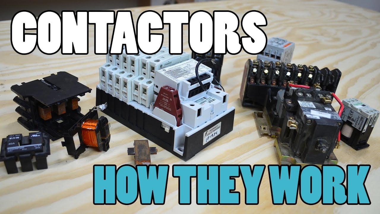
Mira el video educativo en YouTube.
Preguntas frecuentes
What is the first check for ev battery positive negative contactors?
Confirm the exact command, supply, coil option, and safe measurement points before energizing anything. Then compare the expected feedback and bus-voltage response with the approved sequence.
Can auxiliary feedback prove the main contacts are healthy?
No. It reports mechanism position within its own limits. Combine it with load-side voltage, timing, and the documented circuit state.
Can I use a generic contactor driver or suppression diode?
Only after the coil, driver, polarity, release time, EMC, and protection behavior are approved together. A generic change can create slow release or false diagnostics.
¿Qué debe incluirse en una solicitud de cotización (RFQ)?
Provide voltage, current waveform, switching duty, temperature, mounting, coil voltage, suppression, feedback, insulation, life, and the required drawings and test evidence.
Sources and standards context
- Texas Instruments isolated relay-welding detection note
- Fluke inrush-current measurement guide
- Requisitos de control de energía peligrosa de OSHA
Standards, safety rules, and supplier ratings change by market and product revision. Use the current edition adopted by the project and obtain the full requirements through the responsible engineering and compliance process.





