Le câblage des bornes A1 A2 d'un contacteur est l'étape d'identification du circuit de bobine : confirmez les repères des bornes, la tension nominale de la bobine, les indications de polarité le cas échéant, le type de connecteur et l'alimentation de commande avant la mise sous tension, tout en conservant les pôles de puissance sur une étude de schéma séparée. Utilisez-le pour séparer les contrôles des bornes de bobine des pratiques relatives aux câbles des pôles de charge sur les tableaux CC. Il s'agit d'une liste de contrôle pour les équipes OEM et de tableaux — et non d'un dimensionnement ou d'une approbation pour contactor-a1-a2-wiring-dc-coil-terminals-panel-builders.
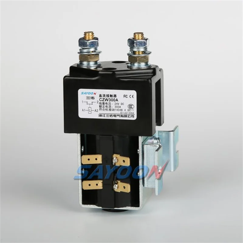
Partie 1. Traitez A1/A2 comme des étiquettes de bobine, et non comme des pôles de charge
Sur de nombreux contacteurs industriels, A1 et A2 désignent le circuit de la bobine. Les pôles de puissance utilisent des repérages séparés. Les revues de câblage des contacteurs A1 A2 échouent lorsque les équipes alimentent les bornes de la bobine en utilisant des méthodes de câbles de puissance ou lorsqu'ils supposent que les habitudes de polarité des bobines CA s'appliquent sans changement à la fiche technique de chaque bobine CC.
Des équipes à la recherche de câblage du contacteur a1 a2 généralement besoin d'une liste de contrôle de projet, pas d'un slogan de catalogue.
Les révisions de bobines progressent plus rapidement lorsque l'indice de révision du plan et les numéros de pièce des connecteurs de faisceau sont associés au code de modèle du contacteur.
Part 2. Confirmer la tension nominale de la bobine avant de raccorder les conducteurs
Lisez la liste des tensions nominales de la bobine sur le modèle installé ou proposé. Un schéma indiquant 24 V CC n'autorise pas un corps de bobine de 110 V. Si la plaque signalétique et la fiche technique ne concordent pas avec le schéma, arrêtez-vous et ouvrez une demande de modification de document — n‘’ essayez » pas une autre alimentation.
| Vérifier | Condition de réussite | Envoyer avec devis |
|---|---|---|
| Plan de repérage des bobines | A1/A2 identifiés en dehors des pôles de puissance | Photo du terminal + dessin |
| Tension de bobine | Le dessin correspond à la fiche technique / plaque signalétique | Valeur américaine requise |
| Type de terminal | Le faisceau correspond à la note du connecteur de la fiche technique | Repère de pièce de connecteur |
| Qualité de fourniture | Mesuré au niveau de la bobine selon la procédure | Avis de relevé de compteur |
| Notes tenues | Impulsion/polarité copiée si bobine de maintien utilisée | Note sur les temps de parcours du chauffeur |
Partie 3. Vérifier le type de terminal et les notes relatives aux connecteurs
Les fiches techniques des contacteurs CC SAYOON indiquent souvent le type de borne de bobine, comme des connecteurs de 6,3 mm sur certains modèles. Assortissez les cosses du faisceau à cette spécification. Les languettes pliées, les embouts sous-dimensionnés et les ponts volants sont des défauts de terrain courants qui ressemblent plus tard à des pannes de bobine.
Important : Ne pas raccorder les conducteurs de la bobine tant que la tension du dessin Ue ne correspond pas à la fiche technique du modèle installé et à la plaque signalétique.
Partie 4. Dissocier la qualité de l'alimentation de commande de la responsabilité du contacteur
Une tension insuffisante, des alimentations bruyantes et des retours communs peuvent empêcher l'enclenchement ou provoquer des vibrations. Mesurez l'alimentation aux bornes de la bobine dans les conditions de charge définies par la procédure du projet. Remplacer le contacteur sans vérifier l'alimentation gaspille des composants et dissimule la véritable panne.
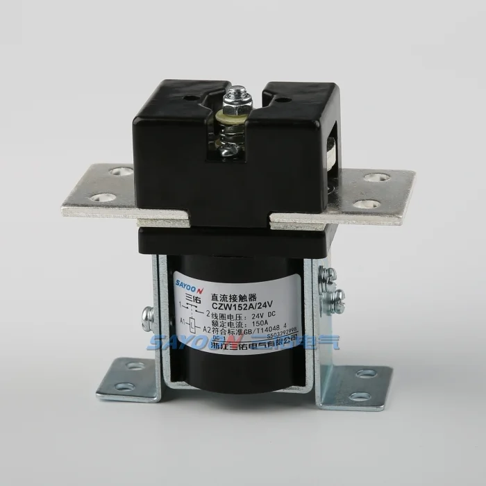
Partie 5. Garder les notes d'impulsion de la bobine de maintien visibles lors de leur utilisation
Les modèles de maintien magnétique peuvent nécessiter des notes sur la durée des impulsions et la polarité, contrairement aux bobines continues. Si le panneau utilise une bobine de maintien, reportez ces contraintes de la fiche technique dans le descriptif de commande. Une hypothèse de 24 V continus sur une bobine à impulsion-maintien est une erreur de conception, pas une préférence de câblage.
Partie 6 : Itinéraires des produits après la documentation du circuit de la bobine
Discutez des voies de maintien magnétique CZW normalement ouvert ou CZW-K uniquement après avoir noté la tension de la bobine et le type de borne. Ne copiez pas les suppositions de câblage de la bobine d'un contacteur d'éclairage AC sur une bobine DC sans vérifier la polarité et la tension nominale sur la fiche technique.
| Situation | Route SAYOON | Pourquoi on en discute |
|---|---|---|
| Trajet de bobine NO continu | CZW100A / CZW400A | Examen de la borne de bobine NO standard |
| Panneau de bobine de maintien | Famille CZW50A-K | Appliquer des notes de type pulsation et maintien |
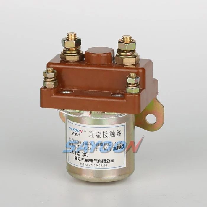
Les routes des produits sont acheminées après la documentation des entrées :
- Contacteur DC normalement ouvert CZW100A — révision du type de borne de bobine après documentation de l'approvisionnement.
- Contacteur CC normalement ouvert CZW400A — circuit NO à courant plus élevé avec notes de bobine de la fiche technique.
- Contacteur DC à maintien magnétique CZW50A-K — discussion sur la borne de la bobine de maintien lorsque les notes d'impulsion s'appliquent.
Après les contrôles A1/A2, ouvrez le Contacteur CC série CZW pour le contexte familial, ou contacter SAYOON avec des repères « Nous » et de connecteur.
Lectures complémentaires : Contacteur CC série CZW; guide étape par étape pour le câblage d'un contacteur basique; Guide de câblage de contacteur à bobine 120V.
Part 7. Ajustement de la limite pour les examens du câblage des bobines
Limite de montage : identification des bornes de la bobine CC et examen de l'alimentation de commande ; il ne s'agit pas d'une approbation de câblage sous tension, d'une liste de points de consigne ni d'un substitut aux schémas du projet. Cette page n'approuve pas un panneau sous tension et ne remplace pas la procédure de l'électricien responsable.
FAQ
Que signifie généralement le câblage A1 A2 d'un contacteur ?
Il s'agit généralement d'identifier et de raccorder séparément les bornes du circuit de commande de celles des pôles de puissance, conformément à la fiche technique du modèle et au plan du projet.
Est-ce que A1/A2 sont toujours des bornes de bobine CC ?
Les conventions de marquage sont spécifiques à la famille de modèles. Toujours vérifier sur la fiche technique et la plaque signalétique de l'appareil installé.
Que faut-il mesurer avant de rejeter la faute sur la bobine ?
Alimentation de la bobine aux bornes selon la procédure du projet, plus intégrité du connecteur et Us correct.
Comment les bobines de maintien modifient-elles l'examen du câblage ?
Des notes sur la durée d'impulsion et la polarité peuvent s'appliquer ; les hypothèses d'une mise sous tension continue peuvent être erronées.
Que doit-on inclure dans une demande de cotation (RFQ) ou un ordre de modification de conception (ECO) pour le bobinage ?
Type de terminal requis, mode de maintien par rapport au mode continu, repères des connecteurs du faisceau et révision du dessin.
Cette page autorise-t-elle les travaux sur panneaux sous tension ?
Non. Le travail sous tension suit la procédure de sécurité du site et les personnes responsables.





