For a 24v dc contactor coil current review, copy the selected model’s published contactor coil power consumption or current at 24 V DC, state whether pickup and hold values differ, and confirm that the driver, suppression, and control-circuit voltage margin can support that load. This article maps the RFQ fields panel teams and buyers actually need—without treating one internet example as a universal ampere rating.
You will see when a standard DC coil publishes matching pickup and hold power, which datasheet lines belong in the panel record, how to compare coil load to a driver rating, and what to send a supplier when the public page shows a coil-power range rather than a single headline current.
Why coil current belongs in the RFQ packet
Coil load is the electrical price of commanding the contactor. Every 24 V DC contactor coil review should start from that load, not from the main-circuit ampere rating alone. If the RFQ names only the main-circuit current or the words “24 V DC coil,” the control designer still has to guess whether a PLC output, relay driver, or machine interface can survive the duty.
A contactor-coil load note matters for three practical reasons. It sizes the control supply and any inline fuse or protection device.
It tells the reviewer whether pickup demand could exceed a small output stage even when hold demand looks modest. It forces the panel record to name a flyback / suppression diode, varistor, economizer module, or factory-fitted option before copper is cut.
From the field: Installers wiring a 24 V DC coil to an open-collector CNC output often discover the interface limit only after quoting a 500 mA rating and asking where flyback protection belongs. That is exactly the kind of detail an RFQ should settle with published coil data and a stated suppression plan, not after a controller board fails. See the DigiKey TechForum note on 24 VDC relay flyback and PLC outputs.
Inrush vs holding on a DC coil at rated voltage
Start with the published pickup and hold pair for the selected model, not an AC-coil habit.
Many buyers arrive with an AC-contactor habit: a large contactor coil inrush current dc figure and a smaller 24v dc contactor holding current figure. On several standard DC coil families, the datasheet lists the same pickup and hold coil power consumption because the coil is a single winding fed by direct current.
| Pattern | Example source | Pickup / inrush | Hold / sealed | Reader takeaway |
|---|---|---|---|---|
| Equal pickup and hold on a DC mini-contactor family | ABB MC1C/MC2C catalogue data | 3 W average pull-in | 3 W average holding | Treat both fields as the same load unless the selected sheet says otherwise |
| Equal cold pickup and hold on IEC DC conventional coils | Rockwell IEC contactor technical data | 3.0 W pick-up cold | 3.0 W hold-in cold | Use the published wattage at the rated control voltage, not an assumed ratio |
| Different pickup and hold on a 24 V DC motor-contactor example | Schneider LC1D50ABD catalog data | 19 W inrush power | 7.4 W hold-in power | Read both lines; driver sizing must cover pickup |
The table shows patterns only. It is not a substitute for the selected contactor’s current datasheet.
When only coil power is published, coil current can be estimated with I = P / V using the model’s rated control voltage and the pickup or hold wattage line you are designing against. Example: 6 W at 24 V gives 0.25 A, or 250 mA. Use that math only with the selected device’s published P and V, and carry the unit the manufacturer actually prints.
Datasheet fields buyers should copy into panel records
Treat the datasheet as the authority for coil load in the RFQ.
Under IEC 60947-4-1 contactor practice, coil consumption is a measured product characteristic. Your RFQ should therefore copy fields, not invent a single typical ampere value.
| RFQ / panel field | What to copy | Pourquoi c'est important |
|---|---|---|
| Rated coil voltage | 24 V DC and any code suffix | Confirms the control class and ordering string |
| Pickup / inrush power or current | As printed, including separate AC/DC columns if present | Sizes driver peak load |
| Hold / sealed power or current | As printed | Sizes steady-state supply load and holding power / current planning |
| Operating or working voltage limits | Such as 0.85–1.1 × Uc or a stated 0.8–1.2 Us band | Defines allowable supply sag and rise in the working voltage range |
| Suppression / coil circuit notes | Built-in diode, external diode, MOV, economizer | Affects driver protection and release time |
| Ambient temperature for coil data | As printed | Coil power and limits can change with temperature |
If the manufacturer publishes a range rather than one number—as on some heavy DC contactor pages—record the range and ask the supplier which value applies to your coil suffix, ambient, and duty. A range is still useful because it bounds the calculation; it is not permission to skip confirmation.
Matching coil load to driver and cable limits
Once pickup and hold values are copied, compare them to the real control-circuit driver. A 24 V PLC output, relay module, or open-collector interface will list a maximum continuous current and sometimes a peak or inrush allowance. The coil’s published pickup data must fit that hardware decision.
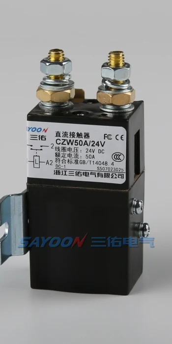
Also copy the coil rated voltage (Uc / Us) working band. On the public CZW50A page, the working voltage range of the 40 °C coil is 0,8–1,2 Us.
At a 24 V rated coil, that band implies an operational window of roughly 19.2 V to 28.8 V before you add project-specific derating. That statement applies to CZW50A only; another model may use different limits.
Cable voltage drop belongs in the same review. Because DC coil current is often steady, a long return path can sag the supply below the device’s minimum operating voltage even when the driver itself is rated high enough on paper. Work the drop estimate with the hold or steady power line unless the economizer section of the datasheet tells you to use pickup.
When pickup power and hold power are different numbers
Economized coil designs need separate pickup and hold lines in the RFQ.
Some 24 V DC contactor families are not single-number coils. Economized or dual-coil designs can publish a high startup demand and a much lower holding demand. As the Schneider LC1D50ABD catalog extract in the comparison table above shows, some 24 V DC motor-contactor coils list 19 W inrush power et 7.4 W hold-in power—a very different driver sizing problem from a 3 W / 3 W standard DC coil.
That pattern changes the RFQ packet in two ways. The driver and supply must tolerate pickup power, not only hold power. The documentation must state whether an external economizer, PWM driver, or factory module is required.
If the RFQ copies only the hold line, the panel may look efficient on paper and still fail the first close command.
How to document coil current for supplier review
A supplier cannot confirm coil suitability from a generic coil-voltage line alone. Send the full model string, including a coil suffix such as /24 V when that is how the manufacturer orders the coil. Add published pickup and hold power or current, driver type and rating, suppression method, ambient and duty notes, and the drawing revision when polarity matters.
Which CZW product fits a documented coil-voltage RFQ?
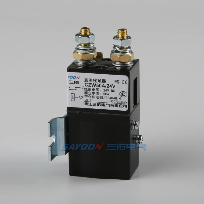
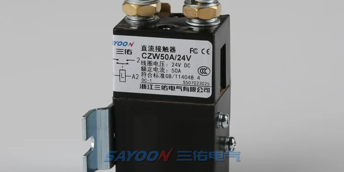
If your requirement already points to the SAYOON CZW family for a low-voltage DC control application, the CZW50A normally open DC contactor page is a concrete example of how coil data appears in the wild. The public table lists 24 V among coil rated voltages, shows coil power (W) 5–10, and gives an ordering example CZW50A/24V. Those statements are limited to CZW50A and do not replace the selected model’s full datasheet.
For a quick internal estimate only, the 5–10 W range at 24 V corresponds to roughly 0.21–0.42 A using I = P / V. Treat that span as a planning band, not an approved as-built current, until the supplier confirms the coil suffix and ambient.
When the main-path requirement fits the CZW family but the current rating differs, continue from the Bloc de contacteurs à courant continu de la série CZW and repeat the same coil-field checklist on the exact model under review.
FAQ
These questions cover the residual procurement checks buyers raise after the checklist sections above.
How much current does a DC contactor coil draw at rated voltage?
There is no single answer for every catalog. Copy the pickup and hold power or current from the selected model’s datasheet at 24 V DC. If only watts are published, estimate current with I = P / V using that model’s rated control voltage.
Do DC contactor coils have inrush current?
Some do, some do not. Several standard DC coil families publish equal pickup and hold power, while economized or dual-coil designs publish separate startup and holding values. Read both lines on the exact sheet you are buying.
What coil fields should I copy into an RFQ?
At minimum: rated coil voltage, pickup power or current, hold power or current, operating voltage limits, suppression method, and ambient temperature for the coil data. Add driver type and cable length when those affect approval.
Can a PLC output drive a contactor coil directly?
Only if the published coil load fits the output rating and protection scheme. Compare pickup current or power to the output limit, confirm suppression, and do not assume that a hold figure alone is enough on economized coils.
How do I calculate coil current from coil power?
Use I = P / V with the coil power line you are designing against—pickup or hold—and the rated control voltage printed for that coil. Do not borrow wattage from another brand or frame size.
What voltage drop matters on a DC control circuit?
Enough drop to push the supply outside the device’s published working voltage band. On CZW50A, the public page lists a 0.8–1.2 Us coil working range at 40 °C; other models may differ.
Is holding current the same as inrush on a DC coil?
Not always. Standard single-winding DC examples often match, but catalog sheets for some 24 V DC contactors list different pickup and hold power. The RFQ should carry whichever pair the manufacturer publishes.
What should I send SAYOON for a coil review?
Send the full model string (for example CZW50A/24V), the coil data you copied, driver and suppression details, ambient and duty notes, and the drawing revision. Use the contact page once the packet is complete.





