An off command does not always mean zero current
DC contactor coil leakage current can come from the off-state behavior of an electronic output, a diagnostic circuit, an indicator or another parallel path. A controller can command off while a small current still reaches the coil circuit. Whether that current can delay release, create partial excitation or produce an abnormal indication depends on the exact coil, driver and suppression arrangement. Compare documented off-state output behavior with the contactor's release requirements, and measure the real circuit safely. Do not assume that every residual voltage means a failed contactor or that one resistor fixes every case.
This guide focuses on unintended current when the output is commanded off. It is separate from normal pull-in and hold-current measurement, from supply voltage tolerance and from intentional PWM coil economizing. That distinction matters because the corrective action depends on where the residual energy comes from.
Start with a complete control-circuit drawing
Mark the control supply, output type, coil terminals, common return, suppression components, indicator devices and diagnostic connections. Include wiring through connectors and shared returns. Identify whether the output is a transistor, a relay contact or a solid-state relay; the label “PLC output” is not a sufficiently precise circuit description.
Record the exact contactor suffix and whether it contains a diode, economizer or other electronics. Do not infer the internal circuit from the number of external terminals or the appearance of the housing. A simplified drawing that omits an illuminated terminal, test circuit or shared connection can hide the path responsible for an off-state symptom.
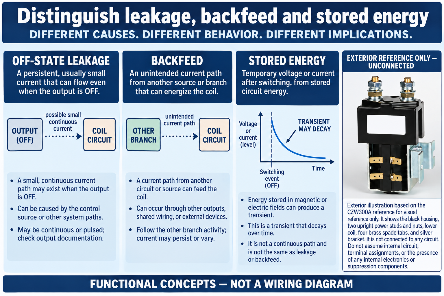
Distinguish leakage, backfeed and stored energy
Off-state leakage is current that the output specification allows or describes while the switching element is off. Backfeed is current arriving by another route, such as a shared circuit or indicator arrangement. Stored energy can produce a transient after switching even when no continuous path remains. The symptoms can look similar on a basic meter but require different investigation.
A suppression device can affect the release transient without being the source of steady off-state current. An internal economizer can also change how input voltage and current relate. Separate the steady condition from the transition immediately after the command changes. Record whether the observation persists, decays or repeats with a diagnostic cycle rather than assigning a cause from one snapshot.
Why voltage alone can mislead
A high-impedance voltmeter can indicate voltage across a circuit that has little available current. That reading is not proof that the coil receives enough energy to operate. Conversely, a small measured average can conceal pulses or intermittent behavior. Select a measurement method that answers the actual question and is approved for the circuit.
Do not short the coil supply, bypass the output or add an arbitrary low-resistance load simply to make the meter reading disappear. Such actions can damage the driver or defeat diagnostics. A qualified engineer may define a suitable loaded measurement, current measurement or time-resolved capture, taking account of instrument connections and the circuit's documented limits.
Compare the right specifications
Obtain the driver's maximum off-state leakage under its stated conditions, diagnostic behavior and switching configuration. Obtain the coil's applicable pickup, hold and dropout information, including temperature and any internal circuit restrictions. A nominal coil voltage is insufficient to decide whether release will be reliable.
Do not convert a published dropout voltage into a universal permissible leakage current using a cold resistance measurement when the coil contains electronics or the operating condition is different. Even for a simple winding, resistance changes with temperature. The equipment designer should establish the appropriate comparison and test envelope. If a required specification is missing, request it rather than replacing it with a convenient rule of thumb.
Use a diagnostic decision table
The following table separates observations from possible causes and next checks. It is a starting point for a controlled investigation, not proof that a particular component has failed. The actual drawing and manufacturer specifications remain the basis for test and acceptance decisions.
| Élément d'évaluation | Preuves à recueillir | Decision boundary |
|---|---|---|
| Steady voltage with off command | Off-state current or another parallel path | Review output specification and full circuit |
| Decaying voltage after opening | Stored energy or suppression transient | Capture the release event with suitable equipment |
| Symptom on one channel only | Channel configuration, wiring or damage | Compare approved settings and actual connections |
| Changed behavior after indicator removal | Possible parallel current path | Review and validate an approved final circuit |
An illustrative resistor calculation and its limits
A parallel resistance is sometimes considered to divert a known small off-state current, but it is a circuit change that requires design review. For an ideal current source, V = I × R gives a preliminary voltage estimate. For a hypothetical 1 mA current and a 10,000 ohm resistor, the calculated voltage is 10 V. At a hypothetical 24 V on-state supply, that resistor would dissipate P = V² / R = 0.0576 W. These are arithmetic examples, not recommended component values.
The real output may not behave like an ideal current source, and the coil remains part of the circuit. Supply tolerance, resistor tolerance, thermal derating, driver capacity, diagnostic function and fault conditions must all be checked. A resistor selected solely from one leakage number can create a misleading result or an unreliable installation. Obtain an approved solution for the exact equipment.
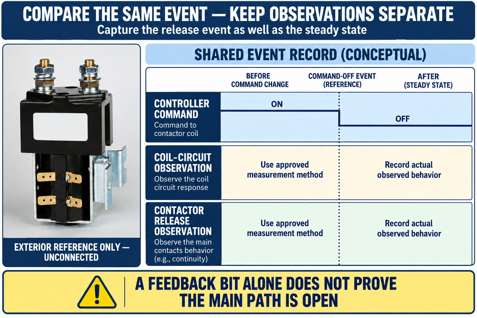
Capture the release event as well as the steady state
Measure the command and coil behavior on an appropriate common timeline where practical. Observe whether the contactor releases normally, releases late, chatters or remains held. Keep auxiliary feedback, main-path electrical behavior and audible observations distinct. A clicking sound or a controller bit alone cannot establish that the power path is safely open.
If the symptom depends on a warm coil, long cable, particular output channel or other operating condition, reproduce only the approved conditions and record them. Avoid repeated uncontrolled cycling of the main load while investigating a control issue. An unloaded coil test can help isolate a question, but it does not validate the final loaded system.
Check shared returns and parallel indicators
Trace the return conductors and common points against the drawing. A shared return with unexpected voltage drop can shift the reference seen by a driver or measurement instrument. An indicator wired across an output, a surge device in the wrong position or a connection to another supply can create a path that is missing from the simplified schematic.
Work from documented connections and measurements. Do not disconnect random conductors on operating equipment to see what happens. Mark any authorized temporary disconnection, preserve the original identification and verify restoration. If the symptom disappears after a change, that is useful evidence, but it does not by itself establish that the final circuit meets its release and fault-response requirements.
Select a remedy that preserves the intended behavior
Possible responses include a compatible output type, an approved interface, revised indicator wiring or a properly engineered loading arrangement. Confirm coil drive capability during pull-in as well as off-state behavior; solving leakage by choosing a weaker output can introduce a new startup problem. Include suppression compatibility and polarity in the review.
Validate the release timing and fault behavior after a change. A diode added casually across a coil may affect release dynamics and may conflict with an existing suppression circuit. An interface device can introduce delay, failure modes and maintenance needs. Document the complete solution and its limitations instead of treating an off-state meter reading as the only acceptance criterion.
Apply electrical safety to the whole assembly
A coil control circuit can be low voltage while nearby main terminals connect to a hazardous battery or DC bus. Qualified personnel must establish the appropriate safe condition for work and verify deenergization under applicable procedures. Opening a control command is not equivalent to isolating every energy source. The linked electrical safety regulation describes deenergization and verification requirements within its jurisdiction and scope.
Use measuring equipment suitable for the expected voltage, energy and environment. Preserve the instrument settings, connection points and observed conditions with the result. NIST guidance on traceability helps explain measurement evidence, but it does not certify the installation or supply a contactor-specific leakage threshold.
Build a useful fault report
Send the exact contactor model, coil option, output module and circuit drawing, including all suppression and indicator components. State the command condition, supply voltage, relevant temperature, measured steady current or voltage, transient behavior and actual release observation. Include the test method and any uncertainty or untested condition.
Ask for a compatibility review of the complete coil-driver interface. Keep a proposed explanation separate from the raw observations: “output commanded off, voltage observed” is evidence; “coil defective” is a conclusion that still needs support. Retain the approved change and validation record with the equipment documentation so that a later replacement does not recreate the same problem.
Product and related engineering references
Review the Sayoon CZW300A product information for exact configuration questions. This construction reference does not establish a storage limit, minimum auxiliary load or off-state leakage allowance. Start the broader application review with DC contactor current classes and confirm all remaining specification fields for the actual equipment.
Related guide: Tension d'enclenchement et tension de déclenchement du contacteur : comment vérifier les deux.
Related guide: DC Contactor Coil Current Measurement Under Pull-In and Hold.
Related guide: Suppression des surtensions de bobine de contacteur : Diode, TVS, RC ou varistance ?.
Sources and limits
Le Solid-State Relay Handbook hosted by MIT describes off-state leakage as a specified and measurable SSR characteristic. It provides general device background; the exact output and coil documentation determines the applicable limit in your circuit.
Electrical safety requirements in 29 CFR 1910.333 support the deenergization discussion within their scope. NIST guidance on metrological traceability explains the basis for measurement records and uncertainty. Neither source supplies Sayoon-specific electrical or storage limits.
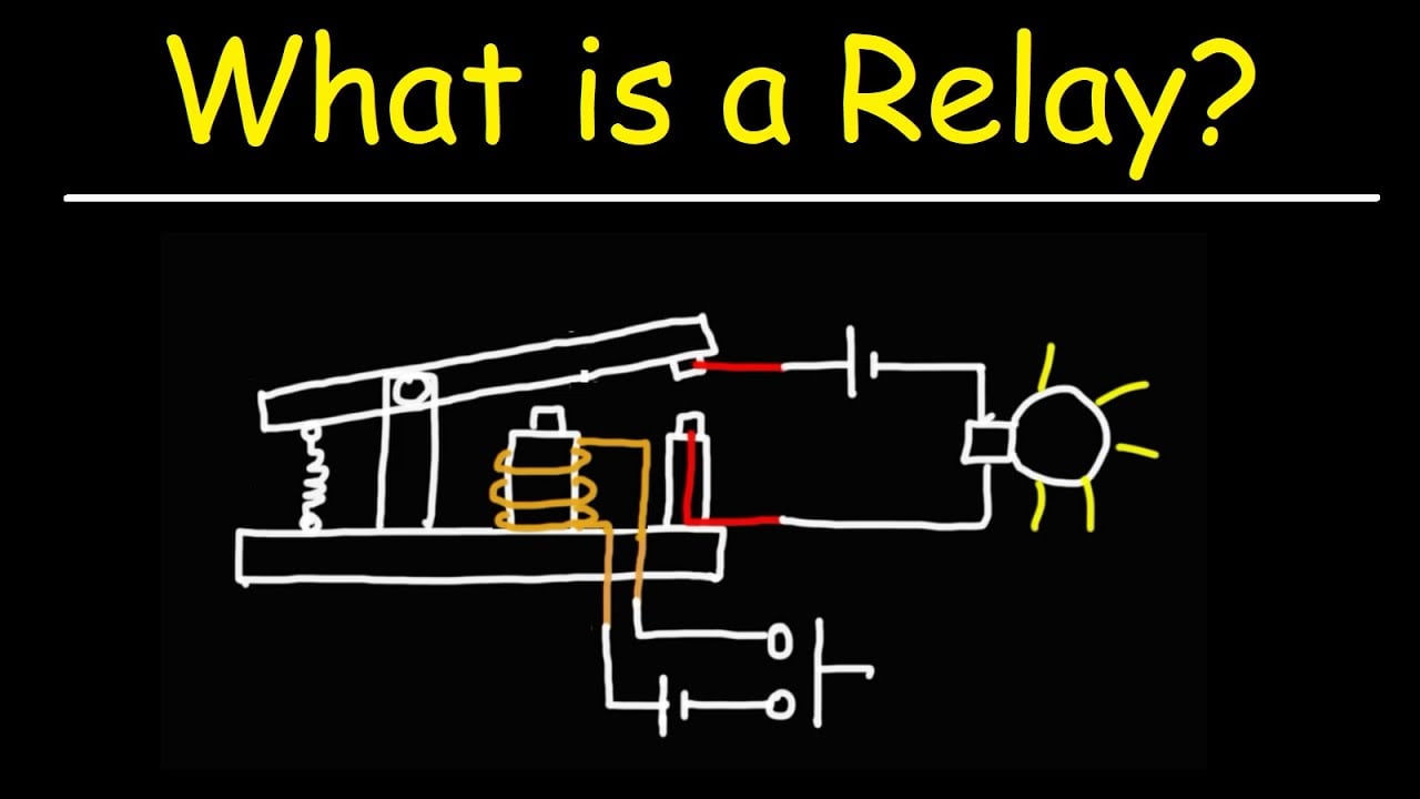
Educational video: mechanical switching and electronic control paths
The Organic Chemistry Tutor explains relay operation and the distinction between the control circuit and switched circuit. Use it as background when reviewing a complete coil-driver circuit. It does not supply a leakage-current allowance, a release-time limit or a measurement procedure for this contactor.
Foire aux questions
Does an off-state voltage prove the coil is defective?
No. The output, diagnostics, parallel devices or stored energy may explain the observation. Identify the available current and timing with an approved measurement method. Preserve the raw observations before drawing a conclusion about the contactor or output module.
Can the dropout voltage be converted directly into leakage current?
Not generally. Coil temperature and internal electronics can change the relationship between voltage and current. Use the exact manufacturer information and a suitable circuit model. A cold resistance measurement is insufficient for an unknown economized or suppressed coil.
Can I add a diode to cure leakage?
A diode is not a universal remedy for steady off-state current. Suppression selection can alter release dynamics and may conflict with an existing circuit. Have the driver, coil and complete suppression arrangement reviewed before modifying the equipment.
What should be measured after a corrective change?
Verify the on-state pull-in capability, off-state behavior, release timing and relevant fault response under the approved conditions. Record actual contactor behavior alongside electrical measurements. A disappearing meter indication by itself does not establish that the final design is acceptable.





