A 96V DC contactor must be selected from both the main-circuit duty and the coil specification. In a product listing, “96V” may describe a battery system, a switching voltage or the coil supply; those meanings are not interchangeable. Define the highest operating bus voltage, continuous current, closing event, interruption event and current direction before choosing a model. Then select the coil variant to match the actual control supply. A contactor advertised with a 96V coil is not automatically qualified to switch a 96V battery under every load condition.
This guide focuses on procurement and selection for equipment using a nominal 96V DC system. It explains what to ask a supplier, what to record in an equipment specification and what must be verified before a replacement or new design is released.
Resolve the three meanings of a 96V listing
Begin by labeling the voltage fields on the drawing. The battery or DC bus supplies the load through the main contacts. A separate circuit energizes the contactor coil. The product may specify another voltage for a particular making or breaking condition. A catalog headline that gives just one voltage leaves an important part of the application unresolved.
If the equipment uses a separate low-voltage control supply, the coil can have a different nominal voltage from the main bus. That does not make the contactor unsuitable by itself; the main contacts still require the correct DC rating. Conversely, a matching coil voltage tells you little about the load path’s thermal or interruption capability.
Ask for the complete ordering code and its corresponding data sheet, rather than accepting a product family description. Mark the coil voltage and main-circuit voltage in different columns of the RFQ. This simple distinction is especially useful when comparing distributor listings that combine several coil variants on one page.
Specify the battery’s full operating range
Nominal pack voltage is a system label, not the highest voltage the contactor will see. Obtain the battery supplier’s charging limits, cell configuration and allowed operating range. Include any other source that can energize the same bus. Do not apply a generic multiplier to every 96V pack: different chemistries and charging arrangements can have different limits.
Record the maximum continuous voltage at the contactor terminals, the operating conditions that create it and any separate transient requirement. Describe whether the bus remains energized on one side after opening. If the equipment includes a charger, generator, regenerative drive or another battery branch, show each connection on the one-line diagram.
That drawing defines what the contactor actually disconnects. Opening a battery branch may leave a charger or capacitor bank connected to a downstream circuit. The required maintenance isolation and discharge arrangements should therefore be reviewed separately from ordinary remote load switching.
Build a duty specification instead of choosing by amperes
| Champ d'appel d'offres | Evidence to provide | Acceptance question |
|---|---|---|
| Main-circuit voltage | Battery maximum, charger limit and connected sources | Does the selected variant cover the actual DC operating range? |
| Courant continu | Load profile, ambient, conductors and enclosure conditions | Is installed temperature acceptable over the assigned duty? |
| Closing event | Motor startup or capacitor inrush, including precharge state | Is making duty supported for the actual circuit? |
| Événement d'ouverture | Expected load current, inductance, direction and repetition | Is DC interruption evidence available for these conditions? |
| Circuit de bobine | Control supply range, driver capability and suppression | Will pickup, hold and release meet the equipment sequence? |
| Protection | Prospective fault and protective-device coordination | Which device clears the fault and what must the contactor withstand? |
This is a decision checklist, not a table of product ratings. Populate it with the exact variant’s approved information and the equipment’s measured or specified operating conditions.
Check continuous heating in the installed assembly
Describe the current profile rather than giving a single peak value. A traction load can alternate between startup, acceleration, cruise and idle; a stationary load can run continuously in a warm enclosure. Specify duration, repetition and cooling conditions so the supplier can evaluate the intended duty.
Terminal joints, conductor size, contact resistance and nearby heat sources affect the installed result. A contactor that passes an open-bench check can still run too hot after cables, covers and adjacent equipment are added. Include the manufacturer’s conductor, mounting and torque requirements in the assembly review, without treating them as optional suggestions.
Confirm whether any quoted current requires a specific ambient condition or mounting arrangement. If the data sheet has no applicable derating information, ask for written guidance or suitable validation. Choosing a larger catalog current alone does not address poor terminal joints, an unsuitable enclosure or insufficient clearance.
Distinguish motor startup from capacitor charging
Closing into a motor and closing into an uncharged DC-link capacitor are different events. For a motor circuit, document the starting and stalled conditions that the contactor can encounter, the drive’s control behavior and the protective response. For a capacitor-fed converter, identify the capacitance, initial voltage difference and precharge arrangement.
Precharge is a system function, not a guarantee created by the contactor. Define when the main contact is allowed to close, how the voltage difference is checked and what happens if precharge does not finish. A main contactor should not repeatedly close into an unresolved inrush condition merely because the control software retries the command.
Do not supply an unsupported inrush figure based only on nominal bus voltage. The circuit impedance, capacitor state and switching sequence matter. Send those conditions to the supplier and retain the evidence supporting the chosen making duty. A failed closing event can damage the contacts even when the steady running current seems modest.
Require DC interruption and direction evidence
DC does not provide the repeated natural current zeros associated with an AC waveform. The contactor’s ability to open the assigned circuit must therefore be supported by its DC ratings and the conditions attached to them. Do not translate an AC rating into a 96V DC rating by matching only current and voltage numbers.
Specify whether opening happens at normal load, after the drive has reduced current, during an abnormal event or during a defined protection sequence. Include the circuit’s inductive behavior and allowed switching repetition. A carrying rating does not automatically mean the contactor can interrupt the same current.
Trace both motoring and regenerative current where relevant. Some designs use directional arc control and have documented terminal orientation. The official IEC 60947-4-1 overview provides the contactor standard’s scope; verify the selected product’s actual duty evidence rather than claiming qualification from the standard’s name.
Match the coil supply and controller
Measure or specify the control voltage at the coil terminals under pickup demand, not just at the power supply with the coil disconnected. Cable drop and the output device can reduce available voltage. Confirm the permitted supply range and whether the coil is continuous-duty, electronically controlled or fitted with an economizer.
Determine pickup demand, holding demand, polarity requirements and suppression behavior for the exact variant. A controller rated for a small signal output may need an appropriate driver rather than direct coil connection. Conversely, adding external suppression without checking an internal device can change release behavior or create an unwanted interaction.
Record the expected state after control-power loss and after supply recovery. Include brownout, commanded stop and failed feedback in the equipment review. Use the coil voltage tolerance guide for a focused review of supply conditions, keeping its purpose distinct from main-circuit voltage selection.
Coordinate protection and plan validation
A contactor is not automatically a battery fault-clearing device. Identify the prospective fault at its location and the fuse, breaker or other protective device assigned to clear it. Establish what the contactor must carry, withstand or interrupt during the event. Follow the approved coordination rather than opening an unsuitable contactor into an uncontrolled fault.
For application context, the U.S. Department of Energy electric-vehicle maintenance overview notes the need for appropriate expertise and precautions around electrical systems. It does not provide a contactor selection rating.
Validation should cover the installed current profile, coil supply range, closing sequence, commanded opening and feedback response in an appropriate facility. For covered workplace electrical servicing, 29 CFR 1910.333 addresses de-energization and verification. Ordinary remote opening does not replace the required safe-work procedure.
Send the supplier an evidence-based purchase request
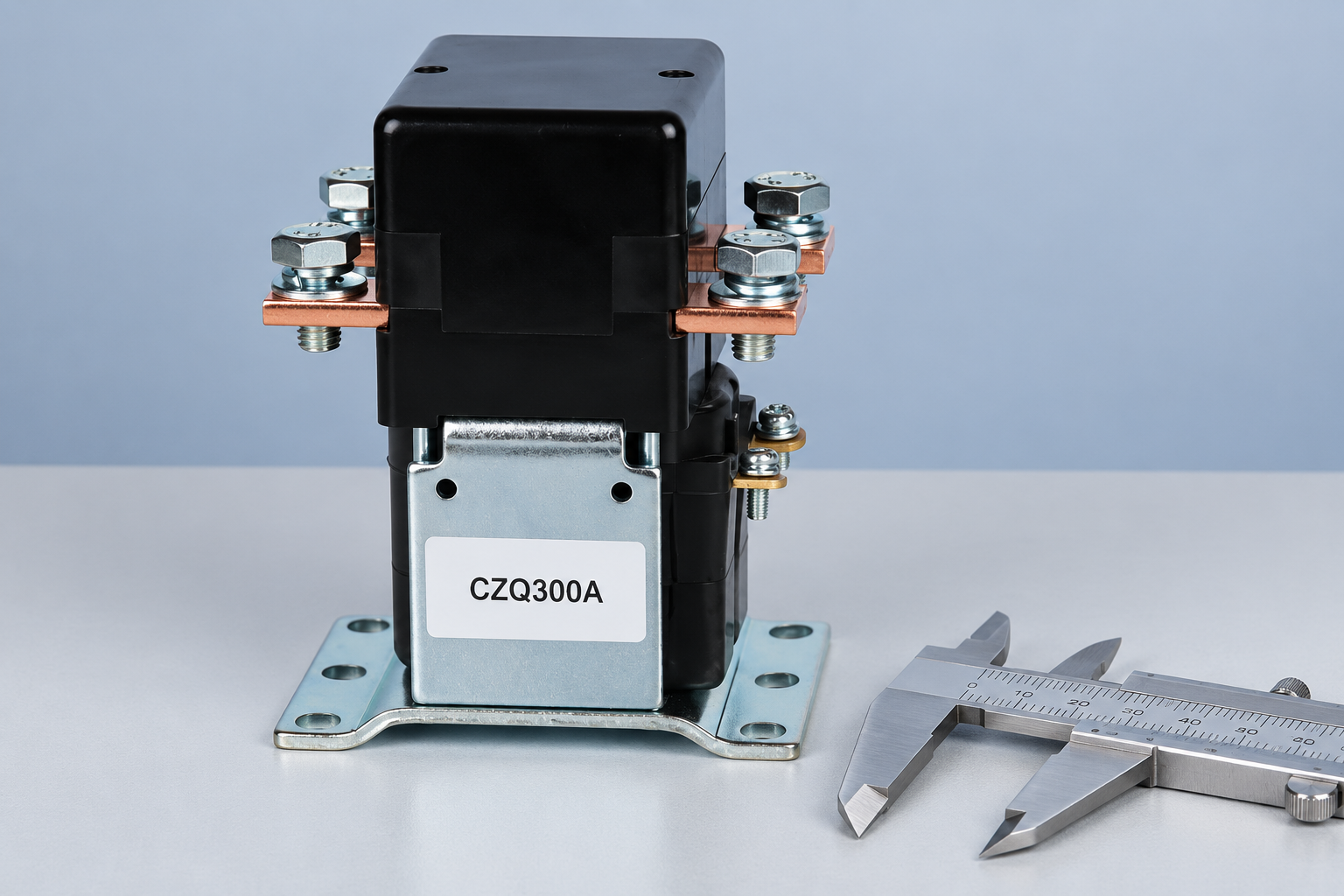
Provide the circuit drawing, voltage range, duty profile, coil requirements, protection coordination, environment and mounting envelope. Ask the supplier to identify the supported ordering code and any unresolved boundary. Review the CZQ300A product information as a construction example, then confirm application-specific ratings and available variants. No 96V variant is promised by the photograph.
Utilisez le OEM specification fields checklist to organize the RFQ. For lifecycle planning, compare mechanical and electrical life. Retain the approved data and test results with the ordering code so future purchasing does not substitute a superficially similar part.
Watch how the electromagnetic mechanism operates
This Electrician U video explains the basic contactor mechanism. Use it for background; it does not establish a 96V battery switching rating or validate a coil variant.

Foire aux questions
Does a 96V coil mean the main contacts are rated for 96V DC?
No. Coil voltage and main-contact switching ratings describe different circuits. Check the exact ordering code’s main-circuit voltage, current and switching duty separately.
Should a 96V battery contactor be selected from nominal voltage alone?
No. Obtain the battery and charger operating limits, connected sources and any relevant transient requirements. The highest applicable operating voltage can differ from the nominal label.
Can an AC contactor be used just because its voltage is higher?
Do not infer DC suitability from an AC rating. Require documented DC carrying, making and breaking capability for the intended circuit and switching events.
What should a buyer send before requesting a 96V contactor?
Send the circuit drawing, full voltage range, current profile, closing and opening conditions, coil supply, protection coordination and installation requirements. Ask for the exact supported variant and evidence.





