Risposta rapida: Select the contactor from the worst-case regenerative current waveform, battery voltage range, DC-link capacitance, thermal environment, and required switching life. Verify bidirectional continuous and peak current, make and break ratings, contact resistance, arc control, coil behavior, and protection coordination. Do not size from the motor’s peak power alone.
EV regenerative braking sends electrical power back toward the battery, so an ev contactor regenerative braking design must consider current in both directions and for changing durations. The contactor may not be switching every regenerative pulse, but it still carries the charging current, sees bus transients, and must open safely when the battery, inverter, or crash controller requests isolation.
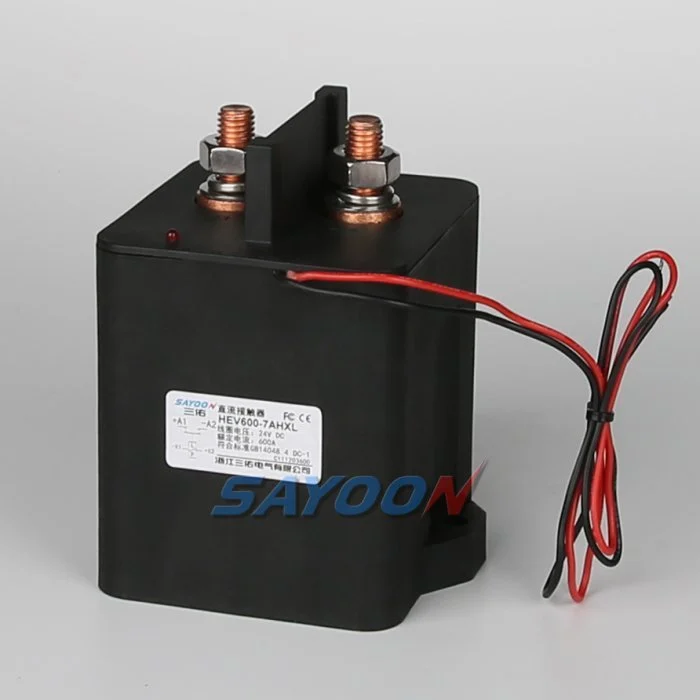
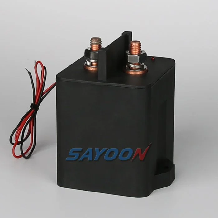
At-a-glance design map
| Element | What it does | Selection or diagnostic focus |
|---|---|---|
| Continuous charge current | Sustained battery-side current during braking | Thermal rise, conductor size and contact resistance |
| Peak regen current | Short pulses during high deceleration | Make/hold margin and current-sensor limits |
| Voltage window | Maximum charged battery and inverter bus voltage | Insulation, arc distance and suppression |
| Switching event | Normal open/close plus emergency opening | Breaking duty, life and fault coordination |
Referenza e ambito del prodotto
The HEV600 high-voltage sealed DC contactor shown in this article is a real Sayoon product reference. See the HEV600 high-voltage sealed DC contactor product page e il Gamma di contattori DC ad alta tensione for the family context. The image does not replace a model-specific drawing review; voltage, coil, current, insulation, duty, and mounting must be confirmed for the application.
Why regenerative braking changes selection
During friction braking, energy becomes heat. During regeneration, the inverter operates as a converter and the battery absorbs current. The battery current can rise quickly when the state of charge, temperature, road grade, or traction limits change. The main contactor may remain closed while the current reverses, so its contacts and terminals must tolerate the bidirectional thermal duty and the associated ripple.
A controller may also open the contactor while current is flowing if the battery becomes unavailable or a fault is detected. The important question is not whether the contactor “switches regen” every time; it is whether it carries and interrupts the worst permitted current under the approved sequence.
Build the current waveform first
Collect battery-side current, DC-link voltage, battery voltage, ambient temperature, and duration for launch, cruise, peak regeneration, friction blending, charging, and fault shutdown. Separate RMS or thermal duty from short peak pulses. Note whether current can reverse while the contactor remains closed and whether a precharge path or diode provides an alternate route.
A simple peak value can overstate or understate the real stress. Use the manufacturer’s test conditions and a representative duty cycle, then add tolerance for sensor error, control delay, temperature, and battery limits.
Bidirectional and DC interruption ratings
Many DC contactor ratings are conditional on polarity, load type, and suppression. Confirm that the selected device is approved for current in both directions and for the maximum working voltage. A contactor that makes a current successfully may have a different breaking limit. DC arcs persist because there is no natural current zero, so arc chambers, magnetic blowout, gas sealing, and spacing matter.
The HEV600 reference shown here is an example of a high-current sealed product. Its actual coil, voltage, current, and life option must be matched to the pack. An engineering review should compare the candidate data sheet with the measured waveform rather than extrapolating from the product name.
Thermal model and contact resistance
Contact losses are approximately current squared times resistance, so a small resistance increase can create a large temperature rise at high regen current. Include busbar joints, lugs, fuse links, and the contactor terminals in the thermal path. Test hot restart and repeated downhill cycles, not only a single laboratory pulse.
Measure contact resistance with a method that excludes cable resistance, then repeat at the expected temperature and after life cycling. A rising value can indicate wear, loose hardware, contamination, or an installation problem that will reduce the current margin.
Interaction with BMS limits
The BMS can reduce regenerative current when the battery is full, cold, hot, or out of balance. Those limits are useful controls but should not be treated as the only protection. A communication fault can leave the inverter with stale limits, and a crash or isolation event can require opening independent of torque commands. The contactor and protection system should remain safe when the normal current-limit message is missing.
Coordinate the BMS, inverter, precharge controller, and contactor driver so a limit change does not create an unintended open under high current. Define the fault priority and timestamp each command and feedback event.
Precharge, opening and emergency events
At key-on, precharge the inverter capacitors before closing the main path. During normal driving, keep the contactor closed while current is controlled. For an emergency open, use the approved sequence: remove torque or gate-drive permission, reduce current if time allows, command the contactor or pyrofuse as specified, and verify discharge. A fixed delay without a current or voltage check can increase arc stress.
The Sayoon opening/closing-time guide and safe testing guide are helpful when defining measurements. Always use the vehicle-specific fault strategy for the final acceptance test.
RFQ data for a regenerative-duty contactor
Provide maximum pack voltage, continuous and peak charge current, pulse duration and repetition, current direction, DC-link capacitance, short-circuit source, breaking requirement, ambient and enclosure temperature, mounting, vibration, coil voltage and suppression, auxiliary feedback, and target life. Include the hottest thermal case and the highest battery state of charge.
Ask the supplier to state the conditions behind every current value. For a production decision, request drawings, insulation data, terminal torque, derating curves, and a sample test plan. This prevents a nominal current label from being mistaken for a validated regenerative-duty rating.
Acceptance record for the engineering team
Before approving this ev contactor regenerative braking decision, create one controlled record that can be read by the design engineer, test engineer, production team, and service technician. List the exact part number and coil option, drawing revision, terminal labels, bus voltage range, current waveform or duty profile, ambient and enclosure temperatures, mounting orientation, conductor size, terminal torque, driver and suppression details, auxiliary logic, HVIL state, measurement instruments, calibration dates, and the pass/fail thresholds. Separate catalogue values from measured values and identify every assumption. If a value is not available, mark it as an open engineering action instead of filling the gap with a typical number.
Run the sequence at the boundaries that matter: minimum and maximum low-voltage supply, cold and warm equipment, the longest approved harness, repeated cycles, and the abnormal state that the safety concept names. Capture command, coil current, feedback, pack voltage, load-side voltage, and fault flags on one time base. After a failed event, stop automatic retries, isolate stored energy, and preserve the first-fault data. A later successful cycle does not erase evidence of a welded contact, slow release, intermittent interlock, or driver protection event. Release the product only when the complete record is reviewed against the current data sheet and vehicle-level requirements. Include photographs of the terminal layout and probe locations, the software build and calibration state, and a short explanation of why the chosen threshold is safe. This makes the result repeatable when a replacement sample, new harness, or firmware revision is introduced.
Related engineering guidance
Usa il Guida alla scelta dei contattori in corrente continua for the broader sizing workflow, the safe contactor test guide for isolation and measurement, and the Guida ai tempi di apertura e chiusura when setting diagnostic windows. For PLC-connected control logic, see the Guida per il controllo della bobina del PLC. These internal links support the decision without replacing the device data sheet or the vehicle safety procedure.
Video educativo
This neutral training video is included for visual context. It is not a product endorsement and the written, model-specific requirements above control the engineering decision.
Guarda il video educativo su YouTube.
Domande frequenti
What is the first check for ev contactor regenerative braking?
Confirm the exact command, supply, coil option, and safe measurement points before energizing anything. Then compare the expected feedback and bus-voltage response with the approved sequence.
Can auxiliary feedback prove the main contacts are healthy?
No. It reports mechanism position within its own limits. Combine it with load-side voltage, timing, and the documented circuit state.
Can I use a generic contactor driver or suppression diode?
Only after the coil, driver, polarity, release time, EMC, and protection behavior are approved together. A generic change can create slow release or false diagnostics.
Cosa dovrebbe includere una RFQ?
Provide voltage, current waveform, switching duty, temperature, mounting, coil voltage, suppression, feedback, insulation, life, and the required drawings and test evidence.
Sources and standards context
- U.S. Department of Energy regenerative-braking overview
- Fluke inrush-current measurement guide
- SAE J1766 electric and hybrid vehicle safety practice
Standards, safety rules, and supplier ratings change by market and product revision. Use the current edition adopted by the project and obtain the full requirements through the responsible engineering and compliance process.





