Risposta rapida: BESS contactor feedback is trustworthy only when the command, coil current, auxiliary contact, string current, and voltages on both sides of the isolation boundary agree within validated timing windows. An auxiliary contact reports mechanism position, not the electrical health of the main path. Fault logic should distinguish driver, coil, feedback wiring, stuck-open, welded, precharge, bus-sensor, and back-feed conditions, then prevent unsafe automatic restart.
This guide turns the topic into a reviewable BESS design, controls, commissioning, sourcing, and service workflow. It uses a real Sayoon product image while keeping every electrical and safety decision tied to the final system, applicable standards, and current product documentation.
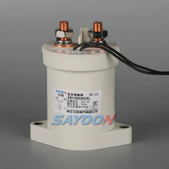
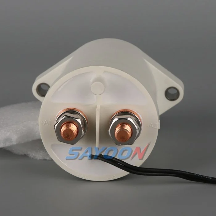
Mappa delle decisioni ingegneristiche
| State or element | Expected condition | Focus sull'ingegneria |
|---|---|---|
| Comando aperto | Coil current ends; auxiliary opens; string current falls | Weld, back-feed, slow release, sensor error |
| Comando di chiusura | Coil current appears; auxiliary closes; bus responds | Coppia aperta, alimentazione debole, meccanismo bloccato, fusibile bruciato |
| Precarica | Bus voltage rises through the approved path | Open resistor, welded precharge, wrong source |
| Offline string | String and bus sides remain independently known | Parallel-rack back-feed or sensing ambiguity |
Referenza del prodotto e confini applicativi
Il SEV200ADXL sealed high-voltage DC contactor is a real product-family example. Review the Guida dei contattori DC ad alta tensione e Guida alla scelta dei contattori in corrente continua for adjacent decisions. A product image, family name, or nominal current is not approval for a particular BESS. Confirm the exact order code, drawing, coil, main-circuit duty, insulation, environment, life, mounting, control, feedback, and protection.
Define feedback as correlated evidence
The controller issues a command, the driver applies coil energy, the mechanism moves, the auxiliary contact changes, and the main circuit changes voltage or current. Each signal describes a different layer. A plausible state requires those layers to agree; it does not require every transition to occur at the same instant. Build explicit states for open verified, precharge active, close pending, closed verified, open pending, discharge pending, and fault latched.
Write expected combinations for startup, charge, discharge, standby, emergency stop, loss of communications, service, and restart. A single generic contactor fault hides the difference between a broken feedback wire and a welded main path.
Check the command and coil driver
A software command proves intent, not actuation. Record driver enable, supply voltage at the coil, coil current, diagnostic flags, and suppression behavior. Low control voltage, a current-limited driver, open winding, reversed polarity, connector fault, or thermal shutdown can prevent pickup. Internal economizers can create a pull-in pulse followed by lower hold current.
Use a model-specific current and timing envelope. A universal coil-current threshold can misclassify an economized product or hide excessive cable drop. After an open command, an extended current tail can delay release.
Understand auxiliary-contact limits
The auxiliary contact normally follows the armature, but it does not measure resistance through the main terminals. It can disagree because of bounce, corrosion, an incorrect NO or NC mapping, insufficient wetting current, overload, a broken wire, or a short to supply. Debounce should reject brief bounce without masking a true delayed or unstable transition.
Inject open-circuit and short-circuit faults at the controller connector during validation. Confirm the input circuitry can distinguish valid states and that a wiring fault cannot be mistaken for safe isolation.
Use voltage and current independently
Measure the battery-string side and common-bus side of the boundary. During precharge, bus voltage should follow the expected curve before main closure. During opening, string current should stop and the isolated section should follow the approved discharge behavior. If auxiliary feedback says open while current continues, suspect a weld or parallel path.
Equal voltages do not always prove a weld because another rack or the PCS can hold the bus near string voltage. Use current, controlled discharge, switch state, and circuit topology to interpret the reading.
Build timing windows from test data
Measure pickup, bounce, settling, release, and voltage response at low and high control supply, cold and hot conditions, and the longest approved harness. Set diagnostic windows from validated distributions with documented margin. A short timeout creates nuisance trips; a long timeout delays isolation.
Store timestamps for command, coil-current change, auxiliary transition, current change, and bus-voltage response. Preserve the first mismatch even if later signals settle, because automatic retry can erase evidence.
Separate fault signatures
A stuck-open condition often shows a close command and coil current without the expected main-path response. A welded condition often shows an open command with continuing current or a bus that cannot be discharged as expected. A feedback-wire fault can show impossible auxiliary logic while coil current and main-path evidence remain normal. A fuse fault can look like a stuck-open contactor.
Diagnostic names should reflect the evidence and uncertainty. Do not direct service teams to replace a contactor until the driver, fuse, conductors, sensors, and parallel sources have been checked.
Control retries and recovery
When the open state cannot be proven, inhibit charging, discharging, and automatic reclose. Command the approved discharge path, stop repeated coil cycling, and retain the fault snapshot. Recovery may require a controlled power-down, absence-of-voltage verification, inspection, and a service-authorized reset.
A later valid transition does not prove the earlier fault harmless. Intermittent harness, marginal pickup, or thermal behavior can return under load. Define which faults latch and which can clear only after an independently verified safe state.
Validate with fault injection
Use production-intent contactors, drivers, sensors, fuses, busbars, software, and harnesses. Inject one fault at a time: open coil, low supply, stuck feedback input, delayed auxiliary transition, missing bus sensor, failed precharge, persistent bus voltage, and simulated back-feed. Verify code, containment, inhibited restart, and retained data.
Repeat at temperature and control-supply boundaries. Record synchronized waveforms, sample identity, software version, instrument settings, acceptance limits, deviations, and reviewers.
Prepare the RFQ and diagnostic map
Provide voltage range, current direction, make and break waveforms, coil option, driver, suppression, auxiliary logic and wetting current, sensor accuracy, timing requirements, precharge, discharge, fault current, protection, environment, switching life, and diagnostic strategy.
The SEV200ADXL shown here is a real product reference, not automatic approval. Confirm the exact ordering code, drawing, auxiliary arrangement, and validated timing for the final BESS.
Controllo della sicurezza e dei dati
Treat batteries, the common bus, converter capacitors, parallel racks, auxiliary supplies, and test equipment as hazardous energy sources until an authorized person has applied the site isolation procedure and verified the required state with rated instruments. Do not bridge feedback, force a coil, defeat interlocks, or open a device outside its qualified switching duty. A simplified schematic can hide stored energy and reverse energization.
Build acceptance limits from exact product data, approved system requirements, and representative testing. Record the complete part number, drawing revision, conductor arrangement, instrument locations, calibration, temperature, software version, raw waveforms, pass/fail limits, deviations, and reviewers. Separate measured facts from interpretations. Record missing evidence as an open action instead of inserting a typical value.
Change control and maintenance
Review the original evidence when the battery configuration, PCS firmware, busbar, fuse, cable, cooling, voltage sensor, current sensor, contactor coil option, driver suppression, discharge component, or operating schedule changes. The assembly may look unchanged while make current, opening current, timing, thermal stress, or insulation has moved outside the validated envelope.
During maintenance, inspect terminals, barriers, conductors, heat evidence, contamination, mounting, control wiring, and stored faults. Compare voltage drop, temperature, and timing only under comparable conditions. After replacing a contactor, fuse, sensor, controller, or resistor, repeat the approved start, load, stop, isolation, discharge, feedback, and restart-inhibit sequence before returning the rack to service.
Guida di Sayoon
Usa il BESS main contactor placement guide, parallel battery-string contactor guide, feedback plausibility guide, Guida alla misura del resistore di precarica, e Guida ai tempi di apertura e chiusura as complementary checks. They address separate decisions within the same controlled boundary.
Video educativo
Cos'è un contattore e come funziona? by Electrician U provides visual background directly related to this topic. It does not replace the written requirements, product data, calculations, or site safety procedure.
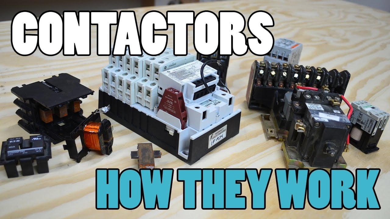
Guarda il video educativo su YouTube.
Domande frequenti
What is the key verification for bess contactor feedback?
Use independent electrical evidence at the defined isolation boundary; do not rely on a command bit, timer, or auxiliary contact alone.
Can an auxiliary contact prove the high-voltage path is safe?
No. Correlate it with voltage, current, coil behavior, timing, and every possible parallel or back-feed path.
Can one universal timing limit be used?
No. Establish timing from the exact contactor, driver, suppression, sensors, capacitance, temperature, supply, and approved system tests.
What belongs in the design record?
Keep the circuit boundary, exact parts, drawings, operating waveforms, calculations, test conditions, raw data, acceptance criteria, deviations, and approvals.
Riferimenti autorevoli
- OSHA 1910.147 — Controllo dell’energia pericolosa
- OSHA 1910.333 — Pratiche di lavoro elettrico
- IEC 60947-4-1 — contattori e avviatori di motori
- Dipartimento dell’Energia degli Stati Uniti — stoccaggio dell’energia
Utilizzare le edizioni e i requisiti adottati dal progetto. Le norme e i dati sui prodotti possono cambiare, quindi il team di ingegneri responsabile deve confermare la progettazione finale.





