Un electrolyzer DC contactor should be selected from the actual rectifier-to-stack circuit, not hydrogen production capacity alone. Specify the highest DC voltage, continuous and transient current, current direction, normal shutdown sequence, emergency interruption duty, fault protection, coil supply, feedback, and enclosure conditions. Confirm these requirements against the exact contactor ordering code and application evidence. A contactor can provide controlled circuit switching, but it does not automatically provide short-circuit protection, maintenance isolation, or approval for a hydrogen hazardous location.
This guide helps equipment builders turn a stack and power-supply specification into a reviewable contactor requirement. It covers the electrical boundary between the converter and stack; gas handling, ventilation, explosion protection, process shutdown, and functional safety require their own qualified engineering assessment.
Start with the rectifier-to-stack boundary
Draw every source and return path before selecting hardware. Identify the rectifier output, stack terminals, output capacitors, parallel converters, discharge resistors, sensing circuits, and any auxiliary supply that can backfeed the boundary. Mark exactly which conductor or conductors the proposed contactor interrupts. A drawing that shows only a rectifier, one switch, and a stack can conceal retained energy and unintended current paths.
Il U.S. Department of Energy explanation of electrolysis describes electricity-driven water splitting and distinguishes electrolyzer technologies. Those process differences do not establish a universal contactor rating. Obtain the specific stack operating envelope, converter characteristics, and shutdown requirements from the equipment documents. The contactor specification must follow that particular system.
Separate three functions in the design review: routine switching, abnormal-event interruption, and safe access for maintenance. The same device may contribute to more than one function only where its documentation and the system assessment support that use. An open command is not proof that every accessible point is deenergized.
Specify voltage and current as an operating envelope
Use the maximum voltage that can appear across open contacts, including permitted converter output, transients, and the stack-side voltage under relevant operating states. Nominal stack voltage is only one operating point. Document the difference between normal regulation, startup, standby, shutdown, and a converter fault. Identify the insulation requirements for adjacent conductors and the enclosure as well as the contact gap.
Continuous current must be assessed under the installation’s actual temperature, conductor size, terminal arrangement, and cooling conditions. A catalog current value cannot be transferred to a hotter enclosure without checking its stated test conditions. Record ripple and repeated operating cycles where they affect heating or contact wear. Include the busbar and joint design in the thermal evaluation.
Make current and break current are separate requirements. A contactor that carries the stack current after closing may face a much more demanding duty when it closes onto capacitance or opens before the converter has reduced current. Ask the supplier for switching evidence at the relevant voltage and circuit characteristics, rather than treating the continuous-current number as an interruption rating.
Write the switching sequence before choosing the device
A normal stop may first command the power converter to reduce output, confirm the intended electrical state, then open the contactor. That sequence must be approved for the stack and converter; it is not a universal operating instruction. Record the required current threshold, permissible delay, feedback condition, and response when any confirmation is missing.
Emergency events need a separate analysis. If control power disappears while the stack current remains high, a normally open electrically held contactor may begin opening before the converter has completed its ramp. Determine whether that interruption is within the device’s documented capability. If it is not, revise the protection and shutdown architecture rather than assuming that a software delay solves loss of power.
Consider startup as carefully as shutdown. Output capacitors, filters, and parallel converter sections can create charging current when a boundary closes. Any precharge sequence needs a defined completion condition and a response to timeout or welded contacts. The stack vendor’s constraints must govern allowed voltage and current transitions; a generic battery precharge recipe should not be applied without review.
Use a requirement table that purchasing can verify
| Requirement | Prove da raccogliere | Reason for rejection or redesign |
|---|---|---|
| Open-contact voltage | Maximum voltage on both sides of the boundary in startup, stop, and fault states | Only a nominal stack voltage is supplied |
| Thermal carry duty | Current profile, enclosure temperature, conductor and terminal conditions | Catalog current has no applicable installation conditions |
| Closing duty | Capacitor charging profile and validated sequencing | Closing current is unknown or exceeds documented duty |
| Opening duty | Current, voltage, direction, circuit time constant, and operation count | Emergency opening is assumed to equal normal ramped stop |
| Fault coordination | Protective-device characteristics and approved coordination assessment | The contactor is expected to clear every prospective fault |
| Control and feedback | Coil limits, suppression option, timing, and independent state checks | An auxiliary indication is treated as complete isolation proof |
| Ambiente | Enclosure, pollution, vibration, temperature, and location classification | A sealed-looking housing is assumed to be hydrogen approved |
This is an engineering decision table, not a table of certified product limits. Populate it with approved drawings, manufacturer evidence, and measured system data. The NREL renewable electrolysis system report provides system-level context for stack and power-supply specification development; it does not certify a contactor selected for a different project.
Coordinate protection and current direction
Identify the maximum prospective fault current at the contactor location and the protection expected to act. Include rectifier contribution, stored capacitor energy, and parallel source paths. Determine whether the contactor must withstand the event until another device clears it, interrupt a defined abnormal current, or remain closed during a protective sequence. These are different duties and require different evidence.
Do not assign breaker or fuse behavior to a contactor merely because the device can open a DC circuit. Request the applicable coordination conditions, including the selected protective device and installation details. A qualification for one protective arrangement cannot automatically be reused for a different fuse, cable, converter, or source impedance.
Check possible reverse current during standby, source transfer, converter failure, or retained-energy conditions. Some DC switching designs have direction-dependent interruption behavior. Confirm the permitted terminal orientation and every relevant current direction with the exact product documentation. Avoid relying on a terminal photograph to infer bidirectional breaking capability.
Control power, suppression, and feedback
Specify coil pickup and hold behavior over the actual control-supply envelope, including startup dips, cable loss, shutdown, and a failed auxiliary supply. Distinguish main-circuit voltage from coil voltage. An electrolyzer’s DC output voltage does not tell purchasing which coil option to order.
Coil suppression affects the switching process. A diode, resistor, transient suppressor, or integrated circuit can change release behavior and impose requirements on the driver. Obtain the timing and polarity information for the exact option. Check the complete driver, harness, suppression device, and contactor together, including power loss, rather than qualifying the coil alone.
Use feedback to detect disagreement between commanded and observed state. An auxiliary contact can help supervision, but its meaning and relationship to the main contacts depend on construction and qualification. Where the system needs confirmation of electrical separation, use the approved independent measurements and diagnostic strategy. Define what happens after unexpected voltage, a timeout, or suspected welding.
Keep the electrical enclosure and hydrogen assessment separate
Hydrogen production equipment may have classified locations or process hazards that require additional approvals. The word sealed, an epoxy housing, or a high-voltage rating does not establish suitability in such a location. Confirm the location assessment, enclosure arrangement, ventilation concept, and applicable approvals with qualified personnel. If the contactor is outside the assessed hazardous area, document that boundary instead of implying a general hydrogen certification.
Temperature, humidity, contamination, altitude, and vibration also affect the electrical assembly. Verify the terminal joints, conductor support, insulation clearances, and service access in the final enclosure. Maintenance planning must address stored electrical energy and any associated process energy. For U.S. work, 29 CFR 1910.147 is an authoritative starting point for applicable hazardous-energy control requirements; it is not a replacement for the site’s complete procedure.
Validate the production-intent assembly
Build a test matrix from the operating envelope, not from a single successful room-temperature cycle. Cover the coldest and hottest permitted conditions, supply extremes, repeated normal stops, defined abnormal stops, startup transitions, and applicable direction changes. Perform potentially destructive interruption or fault tests only through an approved safe test arrangement and qualified personnel.
Record command timing, coil voltage and current, main-circuit current, voltage on both sides of the boundary, feedback transitions, terminal temperature, and protection operation. Define acceptance criteria before the test. Include an inspection for abnormal heating, contact damage, loosened connections, and unexpected switching behavior. A demonstration video is not qualification evidence.
For purchasing, preserve the complete model and coil code, suppression option, auxiliary arrangement, drawing revision, terminal hardware, approved installation conditions, and supplier evidence. Request a documented review whenever a supplier proposes a similar-looking replacement. Physical interchangeability does not establish electrical equivalence.
Product review and complementary guides
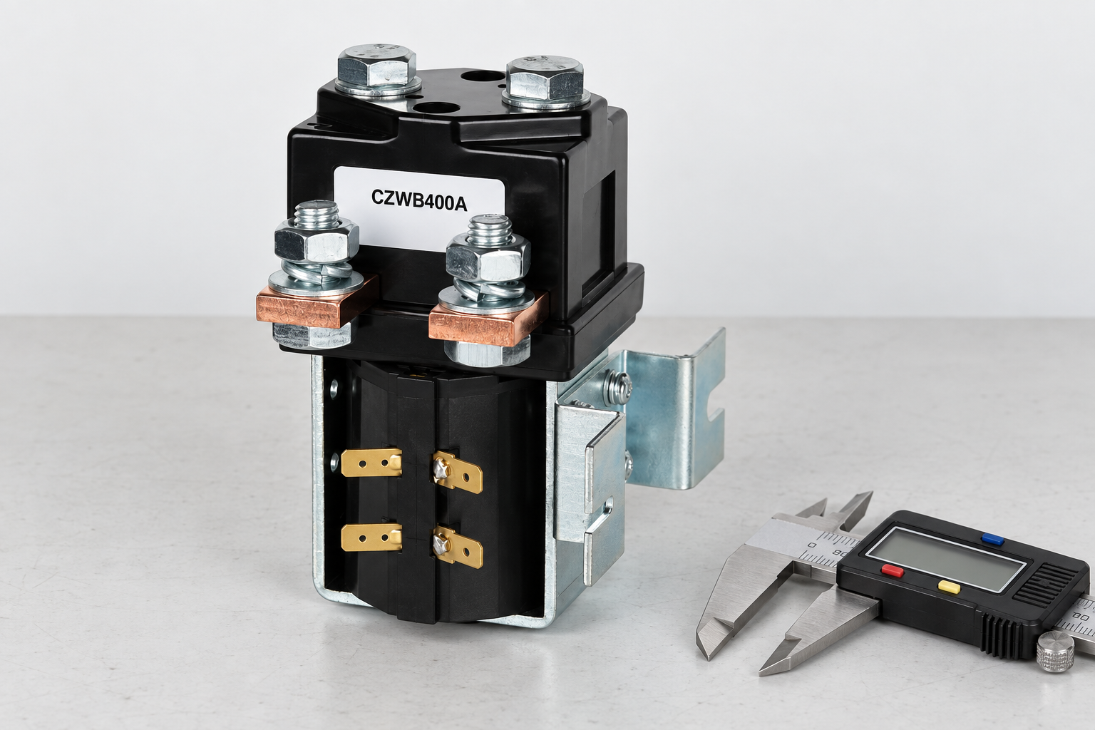
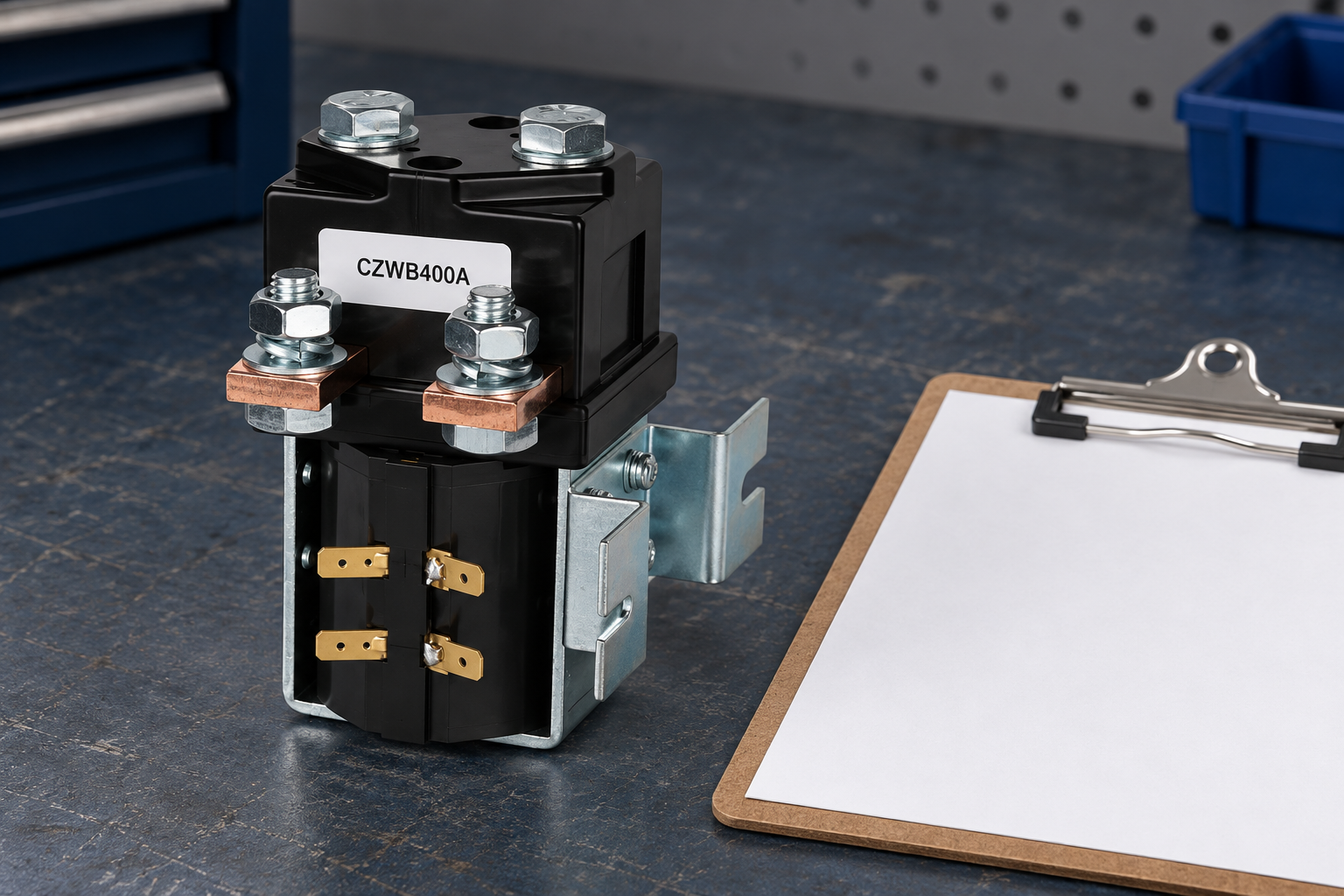
Usa il CZWB400A construction reference as a starting point for a product-document request, not as an automatic electrolyzer approval. Compare requirements with the high-voltage contactor specification guide, il coil voltage tolerance guide, e il mechanical and electrical life comparison. Send the circuit boundary and operating envelope with an inquiry so the proposed device can be reviewed against measurable duties.
CZWB400A is listed as a normally closed construction. It illustrates why the exact contact arrangement belongs in the document review; it is not a default recommendation for an electrolyzer main emergency-disconnect path. Its de-energized state, DC duty and installation would require independent confirmation.
Educational video: electrolysis fundamentals
The U.S. Department of Energy video below explains electrolysis. It provides process background and does not specify switching hardware or establish a safe installation procedure.

Domande frequenti
Can hydrogen production rate determine contactor current?
No. Use the specific stack and power-supply operating envelope, including transient and switching duties.
Can the contactor replace a protective fuse or breaker?
Only functions explicitly supported by its documentation and the approved system assessment can be assigned to it. Do not assume short-circuit protection.
Does a sealed DC contactor have hydrogen hazardous-location approval?
No. Housing appearance and sealing do not establish that approval. Verify the location assessment and required certification separately.
Cosa dovrebbe includere una RFQ?
Provide maximum DC voltage, current profiles, make and break duties, current directions, protection, coil supply, feedback, environment, and the proposed switching sequence.





