A 200V DC contactor must be selected for the highest voltage and switching duty at its main terminals, not just a nominal system label. Identify continuous current, capacitor or motor inrush, expected opening current, current direction, insulation environment and the independent coil supply. A 200V coil option does not establish a 200V main-contact rating. For a nominal 200V battery or converter bus, obtain the actual operating range from the system supplier before requesting a contactor. This guide organizes the evidence an OEM should collect; it does not approve a pictured product for an unspecified 200V circuit.
Identify the source and the disconnect boundary
Put the battery, charger, converter, capacitors and loads on one drawing before comparing parts. Mark which conductors pass through the contactor, where the protection sits and which sources remain connected after it opens. A converter input contactor and a battery pack contactor can have different duties even on the same nominal bus.
For example, opening a battery branch may leave the load bus energized by a charger. A controller that reports open contacts has not thereby established that every downstream conductor is de-energized. Maintenance isolation, voltage verification and capacitor discharge belong in the equipment design separately.
Send the supplier the actual circuit boundary rather than an isolated statement such as “200V, high current.” The boundary determines what voltage can appear across the contacts and what current the device must carry or interrupt.
Replace the nominal voltage with a documented operating envelope
Nominal voltage is useful for naming a system, but it is not always its maximum operating voltage. Obtain the battery configuration and charging limits, or the converter’s regulated range and relevant abnormal conditions. Do not use a universal percentage to convert a 200V nominal pack into a supposed maximum: chemistry, configuration and controls matter.
Record the highest sustained voltage at the contactor terminals and identify the conditions that create it. Describe separate transient or insulation requirements with the appropriate engineering evidence. A component’s insulation withstand figure is not automatically its permitted switching voltage.
If several sources share the bus, review their combined operating modes. A disabled inverter can still be connected to charged capacitors; a stopped motor can become a generator. Each state deserves a defined voltage and current assumption.
Keep the main-circuit voltage separate from the coil
The coil circuit operates the mechanism. The main circuit carries the load. A 200V main bus can use a contactor with a separately supplied low-voltage coil if the selected variant supports both requirements. Conversely, a 200V coil does not establish any particular DC breaking capacity.
Specify the coil supply type, permitted range, pickup demand, holding demand and control-output capability. Identify internal suppression, polarity-sensitive electronics and any economizer. Select these options through the exact ordering code, not from a product-family heading.
During the review, use two distinct voltage fields: main-contact operating range and coil-terminal supply range. This avoids an RFQ in which a distributor quotes the right coil voltage but a different main-contact construction. Confirm the delivered label and approved drawing against the purchase record.
Define carrying, making and breaking duty separately
Continuous current establishes only part of the requirement. Determine the installed load profile and thermal conditions, the current during closure and the current during opening. State how often each event happens. A device that carries a given current continuously may not interrupt that same current under the proposed conditions.
For an inductive load, include the circuit conditions relevant to interruption. For a converter input, identify capacitor inrush and the precharge sequence. Do not transfer an AC switching rating to a DC circuit by matching two headline numbers.
Obtain the applicable DC duty evidence for the exact construction and variant. Where ratings depend on direction or terminal orientation, place that requirement on the drawing. Reverse energy flow, regeneration and multiple source paths must be evaluated explicitly rather than treated as occasional exceptions.
Calculate stored energy without treating it as a switching rating
Capacitor energy illustrates why bus voltage alone is inadequate. For an illustrative 1,000 microfarad capacitor charged to 200V, E = 0.5 × C × V² gives 20 joules, using C = 0.001 farad. This is an invented calculation example, not a product specification or a safe-work threshold.
Stored energy does not tell you the peak closing current. That also depends on initial voltage difference, resistance, inductance and the charging path. Two installations with the same capacitor energy can have different inrush waveforms and different contact stress.
Use the calculation to identify missing system information. Ask how precharge is controlled, how completion is confirmed and what happens if it fails. Do not command repeated main-contact closure into an unresolved charging condition simply because software can retry. Validate the approved sequence in a suitable test facility.
Review insulation and the installation environment
A nominal voltage label does not settle insulation coordination. Document altitude, pollution exposure, condensation, accessible live parts, enclosure construction and the applicable equipment requirements. Ask for the manufacturer’s supported clearances and installation restrictions rather than inventing a universal gap dimension.
Consider terminals and conductors as part of the assembly. A lug that fits a stud can still create an unacceptable clearance, bending load or hot joint. Check the complete mounting envelope, conductor route, fastening instructions and the separation of control wiring from the main path.
If an open-frame construction is considered, the enclosure must address its exposure and accessibility. A sealed-looking contactor likewise does not prove every environmental approval. Record the exact evidence needed for the intended installation and leave unsupported conditions unresolved until the supplier or design authority confirms them.
Coordinate protection before assigning an abnormal opening event
Identify the prospective fault current at the contactor and the device intended to clear it. A high-current contactor is not automatically a general-purpose DC fault interrupter. The protection arrangement may require it to remain closed while another device clears the fault, withstand a defined event or interrupt only a supported current.
Define controller behavior after protection operates. Consider failed feedback, loss of coil supply and restart inhibition. Automatic reclosing should follow the approved equipment sequence and fault assessment, not a generic contactor replacement procedure.
For the RFQ, supply the protective-device information and the intended coordination. A supplier cannot establish system protection from bus voltage and a continuous-current figure alone. Keep the coordination evidence attached to the final ordering code so a later replacement does not silently change the assessed arrangement.
Validate the installed assembly and retain a purchasing record
Plan validation around the complete installation: representative current profile, highest supported operating voltage, mounting, conductors, coil supply range and environmental conditions. Check temperature, commanded opening, main-path response and feedback separately. An unloaded continuity test confirms neither DC interruption nor installed thermal performance.
Review a replacement against the original approved duty, not merely the case size. Changing suppression, contact arrangement or terminal orientation can change operation even when the new device has a higher catalog rating. Use documented change control and record unresolved differences.
The supplier packet should contain the one-line drawing, operating envelope, current profile, switching events, protection, control requirements, environment and drawing revision. Require a written supported variant and evidence for its limitations. Retain those documents with the equipment record and purchasing reference.
Selection evidence checklist
| Review field | Information to provide | Acceptance boundary |
|---|---|---|
| Operating voltage | Actual maximum and connected sources | Nominal 200V alone is insufficient |
| Continuous duty | Current profile and installed thermal conditions | Validate temperature with actual conductors |
| Making duty | Initial capacitor/motor condition and precharge | Obtain applicable closing evidence |
| Breaking duty | DC current, direction and circuit conditions | Carrying current is not breaking current |
| Coil circuit | Supply range, driver and suppression | Separate coil voltage from bus voltage |
| Protezione | Fault source and clearing-device coordination | Do not assume contactor clears every fault |
This qualitative checklist organizes evidence; it does not state product ratings or universal acceptance limits. Numerical examples elsewhere are explicitly hypothetical.
Product information and related review tools
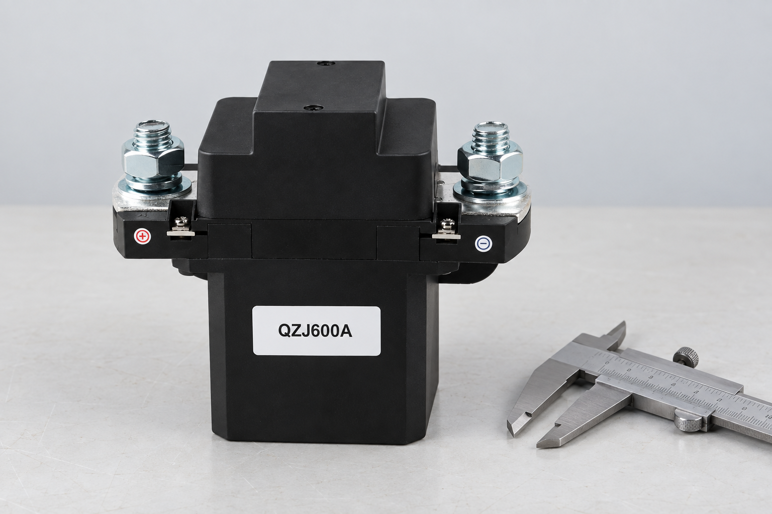
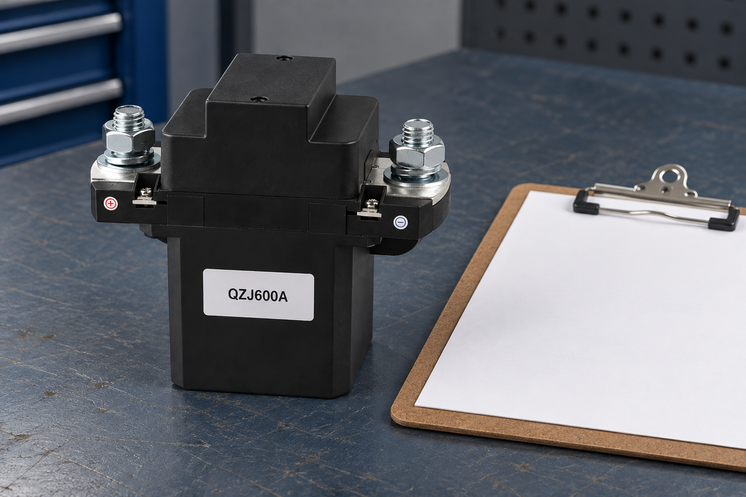
Il QZJ600A product information is the reference for the external construction shown. The pictured variant may have a different current class or contact arrangement from the requirement. It is not an automatic recommendation or a statement that every discussed duty is supported. Obtain the exact ordering code, drawing and applicable ratings before selection.
Usa il OEM specification evidence checklist to separate documented limits from unresolved assumptions. Complement the main-circuit review with coil voltage tolerance e mechanical versus electrical life. Those topics address distinct control and lifecycle questions rather than replacing this article’s assigned selection boundary.
Sources and safe validation
Scope references: IEC60947-4-1 contactor and motor-starter standard overview; U.S. electrical work-practice requirements. Apply relevant equipment requirements and approved manufacturer documentation. These links do not certify the illustrated product for a proposed duty. A commanded contact opening does not replace appropriate isolation and verification before servicing.
Educational contactor mechanism video
Electrician U explains the electromagnetic operating principle. This supports understanding of coil and contact operation, not a particular voltage, current, protection function or pictured variant’s qualification. The article’s selection evidence remains necessary whether or not the video is watched.

Domande frequenti
Does a 200V coil prove 200V switching capability?
No. Coil supply and main-contact ratings describe different circuits. Review the exact variant for both.
Is nominal 200V the maximum battery voltage?
Not necessarily. Obtain the battery and charger operating limits rather than applying a universal multiplier.
Does capacitor energy determine the peak closing current?
No. The charging path and initial voltage difference also determine inrush. Use the actual circuit information.
Can a contactor replace the system fault-protection device?
Only if the complete assigned function is explicitly supported. Do not infer fault-clearing capability from continuous current.





