Risposta rapida: A BESS bidirectional contactor must carry charging and discharging current, but “bidirectional” also needs a precise switching definition. Confirm whether the device may make or break current in both directions, at the full DC voltage and actual circuit inductance. Then verify continuous thermal duty, precharge, fault coordination, coil control, auxiliary feedback, insulation, environment, and electrical endurance for every operating quadrant.
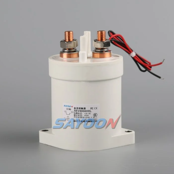
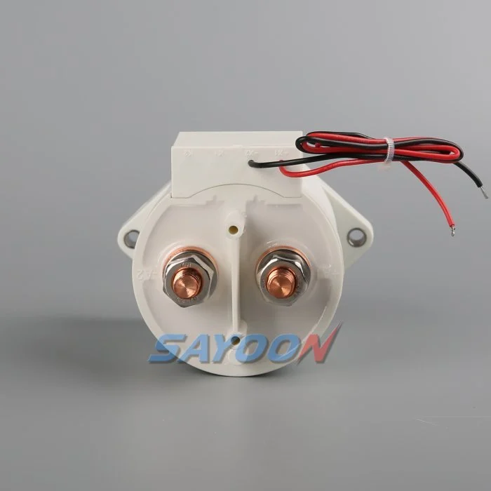
Questa guida trasforma il tema in un flusso di lavoro per la progettazione, la messa in servizio e l’approvvigionamento del BESS, che può essere verificato. Utilizza un vero contattore Sayoon come riferimento visivo del prodotto, mantenendo ogni valutazione, sequenza e decisione relativa alla sicurezza legata al sistema finale e alla documentazione attuale del produttore.
Mappa delle decisioni ingegneristiche
| Stato del sistema | Condizione elettrica prevista | Focus sul design |
|---|---|---|
| Charge | PCS to battery | Continuous heating, charging limits, reverse current |
| Discharge | Battery to PCS | Peak current, bus sag, terminal temperature |
| Normal opening | Current reduced before opening | Residual current and DC arc direction |
| Emergency opening | Abnormal current in either direction | Qualified break duty and fuse coordination |
Referenza e ambito del prodotto
Il SEV400AHXL sealed high-voltage DC contactor è un esempio pertinente di una famiglia di prodotti reali. Guida dei contattori DC ad alta tensione e Guida alla scelta dei contattori in corrente continua per il flusso di lavoro più ampio. Una corrispondenza visiva o un flusso nominale non consentono di considerare un modello adatto per un BESS. Confermate la tensione, il carico corrente, la funzione di apertura e chiusura, la polarità, l’isolamento, la temperatura, l’ambiente, la durata, l’installazione, il driver e la protezione insieme.
Define what bidirectional means
Current can flow toward the battery during charging and away from it during discharge. Carrying current in both directions is not the same as interrupting current in both directions. Internal magnetic arc control can make DC breaking performance polarity-sensitive even when the main terminals look symmetrical. Ask for explicit make and break data for each required direction, voltage, current, load type, and time constant.
Create an operating-state table that lists current direction at closure, during steady carry, and at opening. Include regeneration from the converter, charging from the grid, black-start behavior, DC-coupled generation, and maintenance tests. A state with nominally zero current should still specify a residual-current limit and how the controller verifies it.
Use maximum system voltage
Select against maximum charged battery voltage and defined transients, not only the nominal BESS label. The PCS can impose voltage during startup, shutdown, or a fault. Confirm which terminal may be positive in each state and whether the approved rating changes with polarity. Do not use an AC rating to infer DC interruption capability.
Insulation review covers dielectric strength, clearance, creepage, sealing, pollution, altitude, enclosure geometry, and distances to grounded metal. The completed assembly must be assessed because nearby busbars, sensors, and barriers change the effective insulation path.
Separate carry, make, and break duties
Continuous current drives I-squared-R heating. Make current depends on voltage difference, DC-link capacitance, precharge success, and circuit resistance. Break duty depends on current, voltage, inductance, polarity, contact opening, and protection action. A headline ampere rating does not combine these conditions. Use measured waveforms from charge and discharge operation.
List normal openings separately from emergency interruptions. Normal control should reduce PCS current before opening when the safety concept allows. Emergency duty may be limited to a small number of events, but it must still be supported by evidence and coordinated with the fuse or pyrofuse.
Check thermal performance in both modes
Charging and discharging may have different duration, RMS current, enclosure temperature, and cooling. Fast charging can create a long high-current period after a hot discharge. Model the full daily profile and validate it on production-intent busbars. Measure terminal and body temperatures after thermal stabilization.
Contact resistance, joint resistance, terminal torque, conductor size, surface condition, and neighboring components influence temperature. Use consistent four-wire voltage-drop points where practical. A device can meet average current yet exceed temperature limits during a stacked sequence of charge and discharge events.
Coordinate precharge and polarity
Precharge should reduce the voltage across the main contacts before closure. In a bidirectional system, either the battery or PCS side may be energized first, so the branch topology and resistor stress must be checked for both directions. Confirm blocking devices, sensing, and control logic prevent an unintended discharge through the precharge branch.
Authorize closure from measured voltage difference and stable polarity. Define the response to reversed sensor leads, a welded precharge contactor, open resistor, failed bus sensor, or externally energized PCS. Repeated failed attempts are counted in the duty profile.
Design feedback and fault logic
Auxiliary feedback reports mechanism position within its limits. Correlate it with command, coil current, pack-side voltage, bus-side voltage, and PCS current. If the commanded-open device still shows current or equalized voltage, investigate a weld, back-feed, sensor error, or parallel path. If commanded closed but current cannot flow, check the fuse, busbar, connection, and main path.
Store the first mismatch with direction, voltage, current, temperature, and timing. Avoid automatic retries when the system cannot prove an open state. Fault recovery should require controlled discharge and an explicit safe-state decision.
Validate interruption and protection
Calculate prospective fault current from battery strings and every parallel source. The contactor may only need to withstand current until the fuse clears, or it may be required to interrupt a defined current. These are different duties. Confirm the exact coordination, including current direction and available energy.
Test representative switching on production-intent hardware with the approved protection. Inspect contact resistance, timing, insulation, temperature, and physical condition before and after endurance blocks. A test at lower voltage or favorable polarity does not establish performance in the opposite quadrant.
Build the RFQ around waveforms
Provide minimum, nominal, maximum, and transient voltage; charge and discharge current traces; current at make and break; DC-link capacitance; circuit inductance; precharge; fault current; protection clearing; temperature; enclosure; altitude; vibration; mounting; busbars; coil voltage; driver; suppression; feedback; life; and required standards.
Request a drawing and product-specific evidence for both current directions. The SEV400AHXL shown here is a real product reference, not automatic approval for the application. Final selection requires the exact ordering code and verified duty.
Control changes through service life
Recheck the validated envelope when the battery configuration, PCS firmware, busbar, fuse, cooling, sensor, coil option, driver suppression, or daily operating profile changes. The contactor may look unchanged while make current, opening duty, temperature, release time, or insulation stress has changed. Compare revisions against a controlled baseline and repeat the affected calculations and tests.
During maintenance, inspect terminals, barriers, conductors, heat evidence, contamination, mounting, control wiring, and stored faults. Trend voltage drop and temperature only at comparable current and measurement points. After replacing a contactor, fuse, sensor, or controller, repeat the approved precharge, close, load, open, discharge, feedback, and restart-inhibit sequence before returning the rack to service.
Controllo della sicurezza e dei dati
Trattare la batteria, i condensatori comuni, i convertitori, i rack paralleli, i componenti ausiliari e l’attrezzatura di prova come sorgenti di energia pericolose fino a quando una persona autorizzata non avrà applicato la procedura di isolamento del sito e verificato lo stato richiesto con strumenti di misura nominali. Non collegare i pin di feedback, non forzare la bobina, non disattivare gli interblocchi HV e non aprire un dispositivo al di fuori della sua funzione di commutazione prevista. Una BESS può rimanere alimentata in una direzione che non è evidente sulla schematizzazione semplificata.
Definisca i limiti di accettazione in base ai dati esatti del prodotto, ai requisiti del sistema approvati e alle prove rappresentative. Registra il codice completo dell’ordine, la revisione del disegno, l’opzione per i bobini, la mappa dei terminali, l’allineamento dei conduttori, le posizioni degli strumenti, la calibratura, la temperatura, la versione del software, le forme d’onda originali, i criteri di passaggio/non passaggio, le deviazioni e i revisori. Rileva separatamente i fatti misurati dalle interpretazioni. Quando manca una prova, registra un’azione aperta anziché inserire un valore tipico.
Guida tecniche correlate
Usa il Guida alla misura del resistore di precarica, Guida alla plausibilità del feedback dei contattori, Guida alla resistenza al cortocircuito, e Guida alla coordinazione dell'isolamento come controlli complementari. Queste pagine coprono diverse decisioni e dovrebbero essere applicate allo stesso limite di sistema approvato.
Video educativo
A Look At High-Voltage EV Contactor Technology by CHARGED Electric Vehicles Magazine provides visual background on contactor operation and high-voltage switching. It does not replace the written design requirements or the product-specific validation.
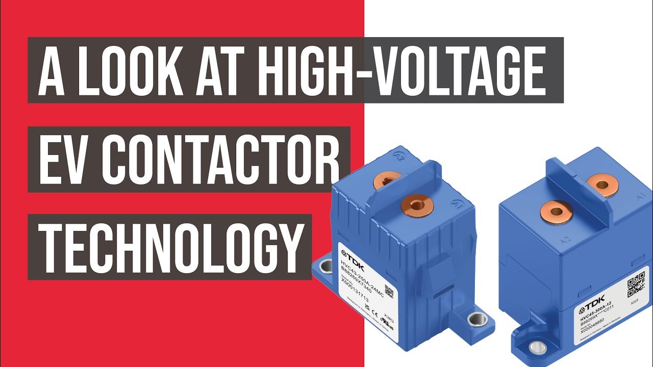
Guarda il video educativo su YouTube.
Domande frequenti
What is the first rule for bess bidirectional contactor?
Definisci i limiti del circuito e ogni sorgente che possa alimentare il circuito, quindi verifica la corretta operatività del dispositivo confrontando le onde di tensione e di corrente misurate con i valori specificati.
È possibile verificare tramite il feedback ausiliario che i contatti principali sono ancora attivi?
No. Correlare lo stato ausiliario con la tensione della linea elettrica, la corrente della stringa, la corrente della bobina, il tempo e tutti i possibili percorsi di retroalimentazione.
Devo sostituire un fusibile a striscia con un contattore?
No. Un contattore fornisce l'interruttimento controllato, mentre un fusibile fornisce la protezione contro i cortocircuiti. Le loro funzioni di resistenza e di arresto devono essere coordinate.
Quali dati devono essere inclusi nella richiesta di preventivo per un contattore BESS?
Includete la gamma di voltaggi, le forme d’onda della corrente, i cicli di accensione e spegnimento, la direzione della corrente, la carica preliminare, i correnti di cortocircuito, la protezione, la temperatura, l’installazione, il controllo della bobina, il feedback e l’obiettivo di durata.
Riferimenti autorevoli
- OSHA 1910.147 — Controllo dell’energia pericolosa
- OSHA 1910.333 — Pratiche di lavoro elettrico
- IEC 60947-4-1 — contattori e avviatori di motori
- Dipartimento dell’Energia degli Stati Uniti — stoccaggio dell’energia
Utilizzare le edizioni e i requisiti adottati dal progetto. Le norme e i dati sui prodotti possono cambiare, quindi il team di ingegneri responsabile deve confermare la progettazione finale.





