Minimum switching current is a low-level signal question
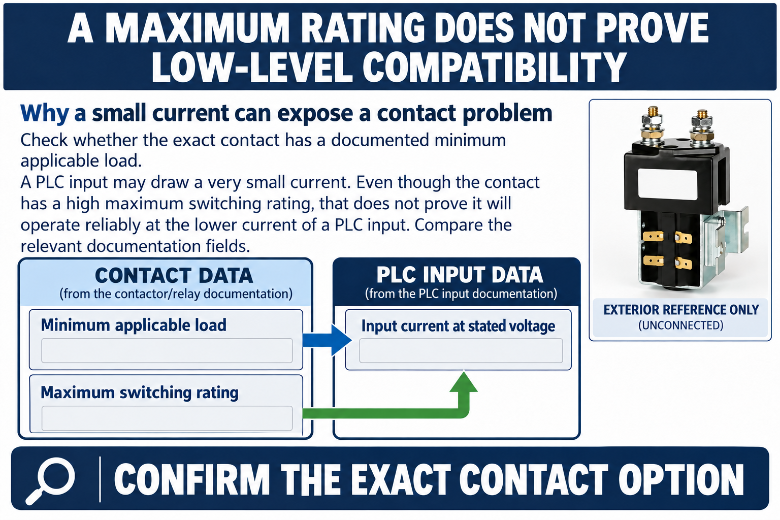
Contactor auxiliary contact minimum switching current describes a lower load condition under which the manufacturer supports reliable contact operation. It is different from the maximum current rating and different from the coil current. A contact that can switch a substantial control load is not automatically suitable for a very small PLC input current. Check the exact auxiliary-contact data together with the PLC input specification, operating voltage, contact material and expected environment. When the minimum load is not published, request confirmation or use an interface whose low-level switching suitability is documented. Do not invent a universal wetting-current value.
This guide addresses the low-current interface between a mechanical auxiliary contact and an electronic input. It does not replace a general auxiliary-contact troubleshooting procedure or determine the safety integrity of a machine. The objective is to help an OEM distinguish a contact-load compatibility problem from wiring, timing, supply and software problems before changing hardware.
Keep three electrical ratings separate
The main contact rating describes the power path. The coil rating describes the actuator supply. The auxiliary contact rating describes a separate signal or control circuit. None can substitute for the others. Even within the auxiliary-contact specification, maximum switching current, maximum voltage, utilization category and minimum applicable load answer different questions.
A large maximum-current number may be useful for a control relay load while saying little about a tiny electronic input. Similarly, a familiar 24 V control supply does not tell you how much current flows through the closed contact. Read the input circuit data for the exact module and input type. Source and sink arrangements, internal resistance and diagnostics can change the relevant behavior.
Why a small current can expose a contact problem
Mechanical contacts have real surfaces rather than perfectly clean mathematical connection points. Surface films, contamination and contact material can affect low-level behavior. Some contact systems are intended for very small signal loads; others require different operating conditions to maintain reliable performance. The applicable value belongs to the contact design and its stated conditions.
Avoid treating wetting current as a repair technique. Increasing current by adding an arbitrary resistor can create heat, exceed output ratings, alter diagnostics or introduce a new fault path. It also may not address incompatible contact material or environmental contamination. The correct action is to establish the actual interface requirement and choose an approved design, not to make a failing input appear stable during a short demonstration.
Read the PLC input data before blaming the contact
Obtain the input voltage ranges for guaranteed on and off states, the input current behavior, any diagnostic pulses and the reference wiring. Confirm whether the input expects a sourcing or sinking field device. Check the common connection and the input filter setting. An indicator light on a module is useful evidence but is not a complete description of the electrical state.
Then identify the exact auxiliary contact, including optional blocks and suffixes. A contactor family page may describe multiple options without establishing that the supplied unit contains all of them. Do not assume the visible small terminals are an auxiliary circuit; they may be coil terminals or another function. Use the approved terminal diagram and maintain separation from the main energy path.
Build a load-compatibility review table
The table below organizes the questions that should be answered before approving an auxiliary contact for an electronic input. It contains decision fields rather than universal numerical limits. Attach the relevant contact and PLC documentation to the completed review so a future replacement can be checked against the same requirements.
| Elemento di revisione | Prove da raccogliere | Decision boundary |
|---|---|---|
| Contact specification | Minimum applicable load and stated conditions | Do not use maximum current as the minimum-load approval |
| PLC specification | Input current, thresholds, common and filter settings | Compare the exact module configuration |
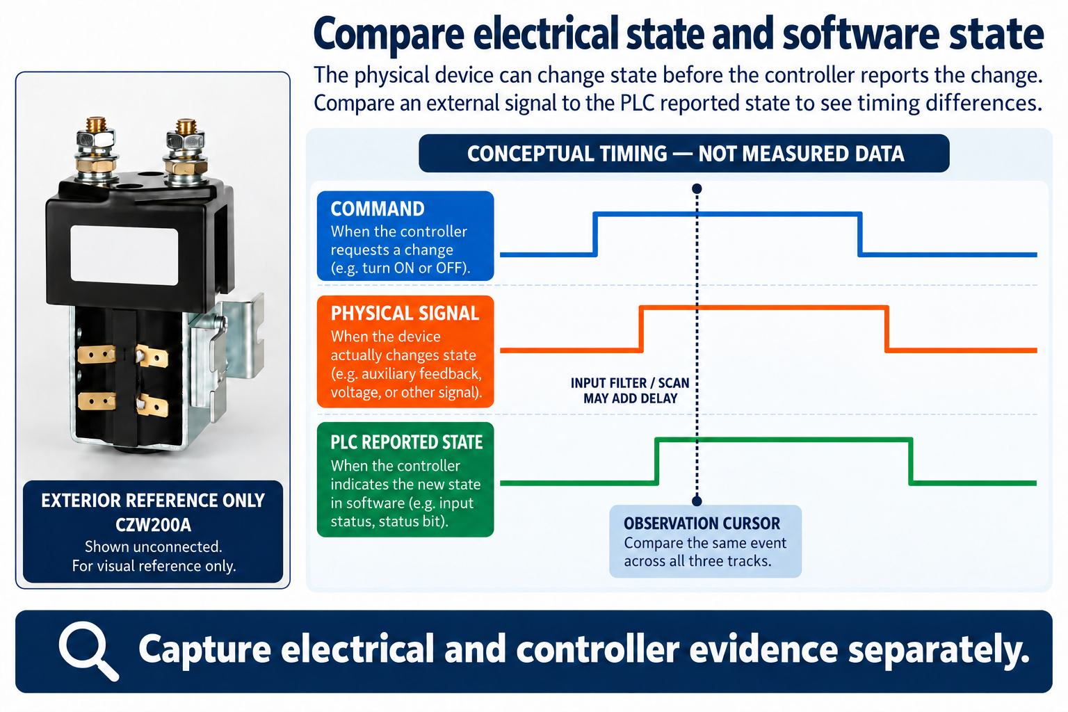
| Measurement | Physical signal and controller state over time | Separate electrical intermittency from software timing |
| Remedy approval | Low-level compatibility, faults and timing | Validate the complete revised interface |
Calculate only when the input model supports it
For an input that the manufacturer represents as an equivalent resistance, a preliminary current estimate is I = V / R. Use volts for V, ohms for R and amperes for I. For an illustrative 24 V source and a hypothetical 12,000 ohm equivalent resistance, the result is 0.002 A, or 2 mA. These numbers are a teaching example, not a Sayoon contact rating or a PLC recommendation.
Many inputs contain nonlinear electronics, protection or diagnostic functions, so a simple resistance model may be inappropriate. Use the specified input current versus voltage or obtain the module manufacturer's guidance. Include supply tolerance and relevant operating conditions. The calculation can identify a question for review; it does not establish reliable switching on an uncharacterized contact.
Compare electrical state and software state
When diagnosing an intermittent feedback indication, record the command, measured signal voltage, auxiliary-contact state, module indication and controller interpretation on a common timeline where practical. A software bit can lag the physical input because of filtering, scan timing or communication. Conversely, an apparently steady software bit may hide short disturbances that a more suitable measurement reveals.
Keep the test method appropriate to the required time resolution. Do not use a slow display to prove that no short interruption occurred. Record instrument settings, the connection method and the observed conditions. NIST measurement-traceability guidance is relevant to the quality of the evidence, but it does not certify your test or establish an acceptance limit for a contact.
Test the interface without creating another hazard
Qualified personnel should define the test and establish an electrically safe condition for installation or adjustment. Isolate the main energy path as required; a low-voltage signal check near a contactor can still expose a worker to hazardous power terminals. Follow the applicable equipment procedures and electrical safety rules rather than treating the auxiliary circuit as permission to work on energized equipment.
If controlled operation is needed for a measurement, specify the boundaries and supervision. Use instruments and leads suitable for the circuit. Never inject a test voltage into an unknown input or bridge a safety circuit to keep a machine running. Preserve the original state and document any temporary test configuration so it can be removed and verified afterward.
Choose a documented remedy
If the actual input load is outside the supported contact conditions, possible engineering responses include a contact option rated for low-level service, an approved interface module or a redesigned sensing arrangement. Each option needs its own voltage, current, timing, isolation and fault-behavior review. An interposing relay adds another mechanical contact and therefore does not automatically solve a minimum-load issue.
If a loading resistor is proposed, calculate its dissipation, component rating, effect on off-state behavior and consequences under relevant faults. Have the circuit designer approve the change. Do not publish a generic resistor value as a universal solution. The aim is reliable state detection over the specified conditions, including environmental and lifetime requirements, rather than a single successful bench reading.
Keep ordinary feedback separate from safety claims
An auxiliary signal can help the controller observe a contactor, but ordinary contact feedback is not automatically a certified mirror-contact or safety-monitoring function. Identify what the particular contact arrangement actually demonstrates and what failure modes remain possible. A closed auxiliary contact alone does not prove that every main pole has the intended electrical condition.
Where the application requires a safety function, the system design, suitable components, diagnostics and validation must satisfy the applicable requirements. This article does not assign a safety performance level. It helps avoid a narrower mistake: selecting a mechanical signal contact from its maximum ampere rating while ignoring the actual small current of the electronic input.
What to send with an engineering inquiry
Provide the exact contactor and auxiliary option, terminal drawing, PLC module and channel type, supply range, expected input current, wiring diagram and observed symptoms. Include whether the problem occurs after long idle periods, in a particular environment or only during switching. Keep measured values separate from inferred explanations.
Ask the supplier to confirm suitability at the stated low-level load and conditions. Request the supporting specification and any restrictions, rather than asking only whether the contact “works with PLCs.” Retain the approved answer with the drawing revision and replacement list. This makes a later purchasing substitution a reviewable engineering change rather than an assumption based on a similar terminal layout.
Product and related engineering references
Review the Sayoon CZW200A product information for exact configuration questions. This construction reference does not establish a storage limit, minimum auxiliary load or off-state leakage allowance. Start the broader application review with DC contactor current classes and confirm all remaining specification fields for the actual equipment.
Related guide: Risoluzione dei problemi del contatto ausiliario del contattore DC: controlli di segnale, tempistica e cablaggio.
Related guide: Come calcolare il valore di carico di un contatto ausiliario di un contattore.
Related guide: Guida alla progettazione del circuito di interblocco dei contatori DC.
Sources and limits
Electrical safety requirements in 29 CFR 1910.333 support the deenergization discussion within their scope. NIST guidance on metrological traceability explains the basis for measurement records and uncertainty. Neither source supplies Sayoon-specific electrical or storage limits.
NI technical guidance on armature relay contact stability explains why a low-level load can behave differently from a larger switched load. It is general contact engineering background, not a specification or endorsement for this product.
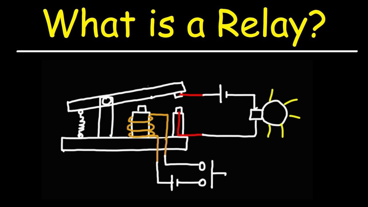
Educational video: separate the coil circuit and the switched signal
The Organic Chemistry Tutor explains how a small control circuit operates a separate switched circuit and distinguishes relay functions. This supports the coil-versus-contact distinction above. It does not establish a minimum switching load, prove PLC compatibility or specify an auxiliary option for the photographed product.
Domande frequenti
Is minimum switching current the same as coil current?
No. Coil current operates the actuator. Minimum switching current concerns the load passing through a specified contact under stated conditions. Keep the coil circuit, auxiliary signal circuit and main power circuit separate when reading specifications and planning measurements.
Does a high ampere rating prove PLC compatibility?
No. A maximum-current rating establishes a different boundary. Check low-level switching suitability and the actual electronic input requirements, including voltage, current and timing. Obtain confirmation for the exact auxiliary option when the minimum-load information is missing.
Can a resistor always fix unreliable feedback?
No. A resistor changes the circuit and may affect heat, off-state behavior, diagnostics and faults. Its suitability depends on the complete design. A documented low-level contact option or another approved interface may be more appropriate than adding load.
Does auxiliary feedback prove the main contacts are safe?
An ordinary auxiliary signal alone does not establish every main-pole electrical condition or a certified safety function. Understand the contact arrangement and system diagnostics. Apply the equipment safety requirements independently of this low-current signal compatibility check.





