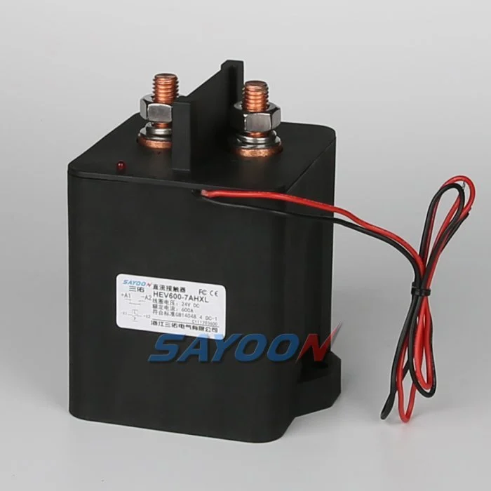
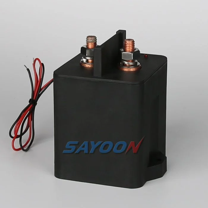

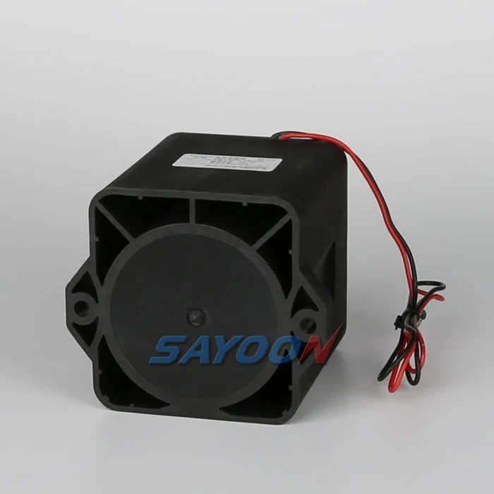
Contatto CC sigillato in resina epossidica ad alta tensione HEV600
Looking for a high voltage epoxy resin sealed DC contactor? Check out the HEV600 for reliable and efficient performance. Contact us for more information
Panoramica
FEATURES
Suitable for new energy electric vehicles, charging facilities, photovoltaic systems, wind power generation systems, automotive air conditioning, communication power, UPS systems, and other electrical control circuits, this switch control device features a compact size, large load capacity, no spark generation, a long service life, and simple maintenance, making it highly favored by users.
1. DC High Voltage Power: The product cavity is filled with a rare mixed gas, enhancing its arc cooling capacity.
2. Control Load Capacity: It supports a load capacity ranging from 30A to 1000A, with a working voltage range of 5-1000VDC.
3. Safety: The insulation structure allows it to operate safely in flammable or hazardous environments, ensuring that the coil and contacts will not oxidize or become contaminated.
4. Compact Design: Compared to similar products, it boasts a smaller size, lighter weight, and lower power consumption.
The product complies with the standards JB2286-78, JB3974-85, YD / 585-92, and YD / T512-92. After undergoing rigorous testing by the factory and relevant testing units, it meets all standard specifications, ensuring that it can be reliably used by customers for many years, effectively addressing their needs with high quality and reliability.
IMPLICAZIONE DEL MODELLO SAYOON
| HEV | 600 | -7 | A | D | X | L | -□ | ■ | /12V |
| 1 | 2 | 3 | 4 | 5 | 6 | 7 | 8 | 9 | 10 |
| 1 | Product type: HEV one group circuits; HEVJ two group circuit |
| 2 | Corrente nominale |
| 3 | Contact Rated Voltage: 1-200V; 7-1000V |
| 4 | Circuit structure: A-Normally open; B-Normally closed; F-Normally open with one auxiliary switch (the auxiliary switch and main contact have the same structure); G-One normally closed with one auxiliary (auxiliary switch and main contact have the same structure). (for other auxiliary switch structures, add 2 or 3 numbers after the model to describe the auxiliary switch structure) |
| 5 | Coil type: D-Single coil; H-With coil economizer; K-Two joint magnetic retention (Single coil, Two joint self-locking); 2K-Three joint magnetic retention (Double coil, Three joint self-locking); P-Signal control; R-Built-in pre charging type [relay drive] (the left digit of the pre charging function is the pre charging delay time, used to control the coil, the right digit is the resistance value with resistance); Y-External pre charging [MOS driver] (The left digit of the pre charging function is the pre charging delay time, and the right digit is used as a lead for controlling the coil. If it is greater than 1, it is the resistance value of the live resistance) |
| 6 | Coil outgoing mode: X-Wire (390mm); O-Other |
| 7 | Mounting bracket type: L-Vertical (default); M-Horizontal |
| 8 | None: Auxiliary switch and main contact have the same structure (default);
2: The structure of auxiliary switch and main contact is opposite; 3: Special auxiliary switch structure |
| 9 | Other special functions: V-With capacitive type load; N-No polarity |
| 10 | Coil rated voltage: 12V, 24V, 36V, 48V, 60V, 72V etc. |
UTILIZZI
The utility model has several significant advantages, including that it is equipped with a normally open contact. This unique design feature makes it particularly suitable for a variety of application scenarios, such as charging piles, electric four-wheel vehicles, new energy vehicles, energy-saving and environmental protection systems, road traffic lighting systems, as well as programmable power supplies and uninterruptible power supply equipment. Due to its flexibility and efficiency, this product can meet the needs of different users, provide reliable power solutions, and ensure safe and stable operation in various environments. In addition, its structural design also takes into account user convenience, making the installation and maintenance process simpler and more efficient.
TECHNICAL PARAMETERS: (Version 3.02)
|
Tipo di prodotto SAYOON |
HEV600 |
| Modulo di contatto | 1 NO(SPST-NO) or 1NC(SPST-NC) |
| Coil Rated voltage (DC V) | 12V,24V,36V,48V,60V,72V,84V etc. |
| Contact voltage (DC V) | 200V,1000V |
| Contact circuit rated load current (DC-1) | 600A |
| Caduta di tensione tipica ai capi dei contatti per 100A | ≯80mV |
| The cooling pull-in voltage at (20±5)℃ (V) | ≯70% |
| The cooling drop-out voltage at (20±5)℃ (V) | ≯35%,≮5% |
| Working voltage range of 40℃ coil | 0.8-1.2Us |
| Drop-out time (n/o contacts to open) | 80ms |
| Pull-in time (n/o contacts to close) | 20ms |
| Maximum bounce time for contact connection | 10ms |
| Maximum bounce time for contact disconnection | 7ms |
| Resistenza di isolamento | 100MΩ |
| Resistenza elettrica | 50Hz/60Hz 2200VAC 1minute |
| Correnti di guasto tipiche che possono essere interrotte | 1500A/5ms at 48V DC |
| Coil power (W) | H: Start 30-60, Keep 4-10 |
| Temperature rise of coil (K) | ≤45 |
| Temperature rise on outgoing terminal (K) | ≤65 |
| Vita elettrica | 20.000 volte |
| Vita meccanica | 300,000 times |
| Specifica di lavoro | Continuo |
| Contact material | Alloy |
| Tempo di inserzione (max) | 130ms |
| Maximum switching current | 2500A 320VDC (more than once) |
| Maximum switching power | 800kW |
| Load terminal type | M10 Screw |
| Coil terminal type | 0.3 square silicone wire, 390mm long |
| Carico nominale del contatto ausiliario (opzionale) | 3A/30VDC |
| Testing organization certification | CE,FCC,RoHS |
Note: Depending on the customer’s different usage environments, the focus of functions may vary. In order to improve the overall performance and adaptability of the product, Sanyou may make necessary parameter adjustments to coil specifications, temperature rise and other related factors. These adjustments are designed to ensure that the product performs optimally in a variety of conditions and meets the specific needs of the user. It should be noted that the above parameters are for reference only, and the specific application results may vary depending on the environment and usage conditions. For more details, see the SAYOON DC Contactor Selection and Use Guide, which provides important insights and advice to ensure you are able to take full advantage of the product and ensure it performs well in your specific application.
CURVA CARATTERISTICA DI CARICO


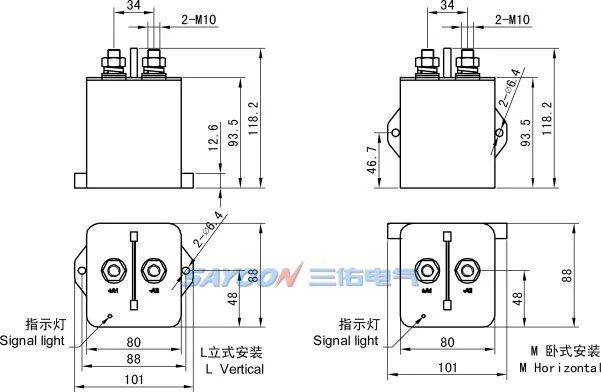
SCHEMA DI INSTALLAZIONE
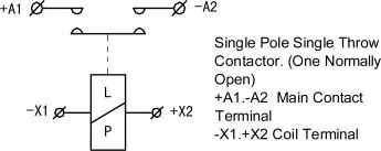
SCHEMA ELETTRICO
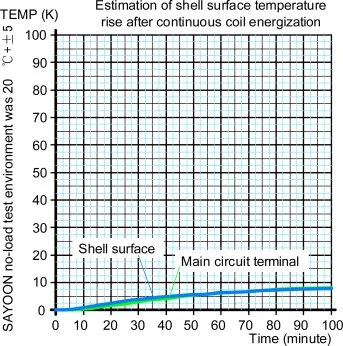
COIL TEMPERATURE CURVE
Abilità meccanica e uso dell'ambiente
| Coppia di serraggio del contatto M10 (N.m) | ≯20.5 appropriate |
| Coil lead mode | Wire dipping tin (red positive and black negative) |
| Temperatura ambiente | -40~+85℃ |
| Umidità relativa | +20 °C 98% |
| Frequenza di vibrazione nella posizione fissa | 3G, ampiezza 1-50 Hz 0,5 mm |
| Commozione cerebrale | (60~100) volte/minuto, accelerazione ≤ 4g |
| Altitudine | 2000m |
| Direzione di installazione | Casuale |
| International Protection | IP68 |
ISTRUZIONE DI ORDINE
|
Tipo di prodotto SAYOON |
HEV600 |
| U.N.W. | 1568g |
| Mounting bracket type | L Vertical(default),M Horizontal |
When placing your order, please be sure to clearly indicate the following basic information: product name, complete model number, control coil voltage specification, mounting frame type, whether auxiliary contacts are required and the required order quantity. For example, you can specify: “High voltage DC contactor HEV600-□-□/24V, 100 pieces”, which means the load rated current is 600A, there is no auxiliary contact, the default installation bracket is, and the coil control voltage is 24V. Total order 100 pieces. Additionally, for products with special voltage specifications, customers may request special orders to meet their specific needs. This information will help us process your order accurately and efficiently, ensuring you receive the correct product tailored to your requirements.
Prodotti correlati
Richiedi un preventivo personalizzato
Sei interessato a questo prodotto? Compila il modulo sottostante e il nostro team di vendita ti ricontatterà entro 24 ore.





+86 130 5791 2357

sayoon@sayoon.com