簡単な回答: Select a solar battery DC contactor from the maximum battery and inverter DC voltage, charge and discharge current in both directions, inverter capacitor inrush, precharge behavior, current at normal and emergency opening, prospective fault current, coil supply, feedback, insulation, environment, and required life. Bidirectional current flow, parallel batteries, chargers, and retained inverter voltage must all be included in the isolation and protection strategy.
This guide turns solar battery dc contactor into a documented selection and validation process using authentic Sayoon product references.
Decision table
| 条件 | Concern | Required check |
|---|---|---|
| System startup | Inverter DC-link capacitance causes inrush | Use verified precharge and voltage-ratio logic |
| Charging | Current flows toward battery | Confirm continuous and directional duty |
| Discharging | Battery feeds inverter and loads | Use worst-case current, duration and temperature |
| Shutdown or fault | Other strings or PV may back-feed | Define boundary, protection, discharge and verification |
Product reference and boundary
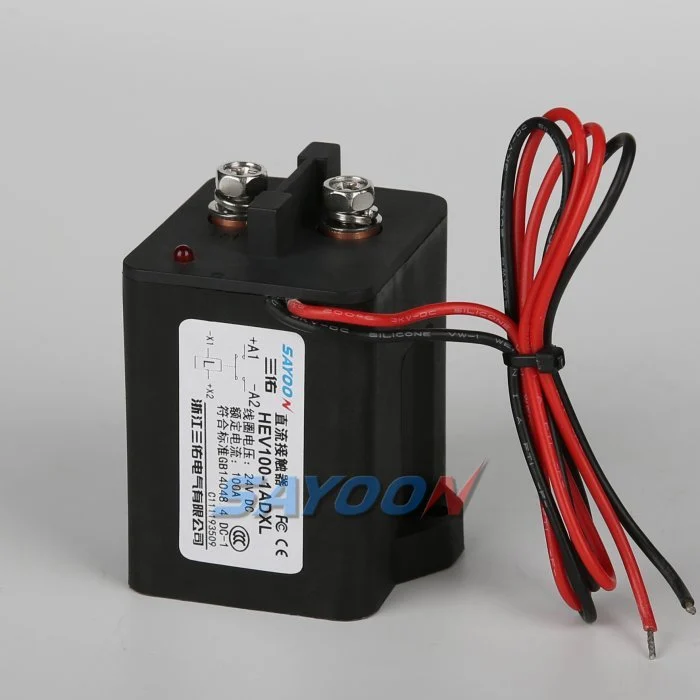
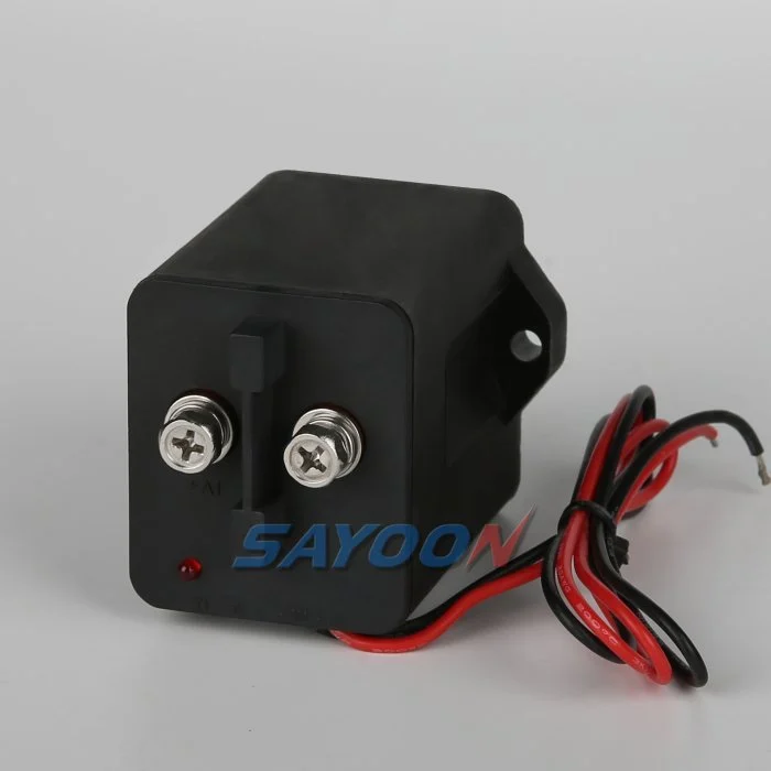
その HEV100-1ADXL sealed high-voltage DC contactor is a product example, not automatic approval. Review the DC contactor guide hub そして selection guide. Confirm the exact ordering code and final duty.
Define the energy boundary
Draw the battery strings, positive and negative devices, inverter, charger, PV-coupled paths, DC/DC converters, precharge and discharge circuits, fuses, service disconnects, sensors, and every parallel source. State which conductors remain energized after each device opens.
An auxiliary contact does not prove absence of voltage. Verify pack-side and bus-side voltage, current, and expected discharge response. Parallel batteries or a grid-forming inverter can keep a common bus live.
Control inverter inrush
Use actual maximum DC-link capacitance and voltage to design precharge. The controller should verify the expected bus rise before main closure, detect an open resistor or welded precharge path, limit retries, and retain fault data.
Closing before voltage equalization can exceed make duty and damage contacts. A successful nominal startup is not sufficient; test capacitance tolerance, low and high voltage, cold and hot conditions, and interrupted sequences.
Coordinate charge, discharge, and faults
Record current direction and magnitude during battery charging, inverter export, load steps, transitions, and protective stops. Determine whether the contactor must interrupt in both directions or whether the inverter and protection remove current first.
Coordinate fuses and other protective devices with the exact prospective fault current and clearing time. Do not assume the control contactor can clear a battery short circuit without product-specific evidence.
Start with measured system duty
Record minimum and maximum battery voltage, charger state, current direction, peak and continuous current, event duration, starts per hour, cooling intervals, ambient temperature, and the longest approved operating cycle. Include cold starts, maximum payload, grades, rapid reversals, stalled mechanisms, emergency stops, and maintenance modes.
A motor label or nominal controller current is not a complete contactor duty. Battery resistance, cable drop, controller limits, hydraulic pressure, route geometry, operator behavior, firmware, and temperature all change the waveform. Capture command, coil voltage, main current, bus voltage, feedback, and temperature on one time base.
Separate carry, make, and break requirements
Continuous-current ratings describe thermal carrying under stated conditions. They do not automatically establish the ability to close into inrush, carry a short-duration overload, or interrupt inductive DC current. Define each event by voltage, current, direction, duration, inductance or time constant, repetition, and fault contribution.
Normal control should reduce current before opening when the architecture allows. Emergency and fault cases require a documented protection sequence. Coordinate the contactor with fuses, breakers, controller shutdown, and every parallel or regenerative source. Do not assign short-circuit clearing to a control contactor without explicit evidence.
Verify coil, driver, and release behavior
Confirm the exact coil option, nominal voltage, pickup and dropout behavior across the auxiliary-supply range, pull-in and hold current, economizer function, polarity, driver current limit, harness drop, and suppression. Measure voltage at the coil during pickup and hold.
A diode, TVS, economizer, or active clamp changes release time and stress. Low voltage can cause chatter and contact damage; excessive voltage can overheat the winding. Set timing and current checks from the final product, driver, cable, connector, supply, temperature, and test distribution.
Review installation and thermal paths
Check mounting orientation, conductor size, lug and busbar alignment, terminal hardware, controlled tightening, cable support, vibration, shock, contamination, moisture, enclosure airflow, adjacent heat sources, and access for inspection. Bench ratings may not represent a crowded system compartment.
Do not use terminal studs to pull misaligned conductors into place. After assembly, inspect seating, washers, thread engagement, barriers, clearances, strain relief, and unintended mechanical load. Trend both terminal temperatures and the body under comparable current and ambient conditions.
Use feedback with electrical evidence
An auxiliary contact indicates mechanism position but does not measure resistance through the main path or prove absence of voltage. Correlate command, driver current, auxiliary state, main current, and voltage across the intended isolation boundary within validated timing windows.
Define responses for stuck-open, welded, delayed pickup, chatter, broken feedback wiring, driver faults, failed sensors, and back-feed. Preserve the first mismatch and raw traces. Block automatic restart whenever switching state or isolation cannot be proven.
Validate the complete system
Test production-intent contactors, controllers, conductors, protection, sensors, cooling, firmware, and enclosures. Cover voltage and temperature boundaries, the longest harness, maximum approved load, repeated cycles, representative regeneration or lowering, and safe fault injection.
Record part numbers, drawings, sample identity, software, instruments and calibration, raw waveforms, thermal conditions, acceptance limits, deviations, and reviewers. A successful no-load close-open test is not evidence for the complete system duty.
Plan service and controlled replacement
Define inspection triggers for abnormal heat, odor, discoloration, chatter, delayed response, voltage drop, nuisance trips, and welded-state diagnostics. Isolate the battery and stored energy under the authorized procedure before touching terminals or replacing parts.
A visually similar solenoid or contactor may differ in coil, duty, polarity, suppression, feedback, mounting, protection coordination, and life. Approve alternates by full ordering code and test evidence, then repeat mechanical, coil, load, stop, isolation, and restart-inhibit checks after replacement.
Prepare the RFQ and change record
Provide battery and control voltage ranges, complete current waveforms, direction, make and break events, fault current, protection, driver and suppression, feedback, life target, switching frequency, environment, mounting, conductor design, standards, and required validation.
Reopen the decision after changes to the battery, charger, motor, pump, inverter, firmware, cable, fuse, coil driver, suppression, enclosure, cooling, route, payload, or maintenance process. Keep assumptions separate from supplier claims and measured results.
Before fleet release, run a documented review that connects every requirement to evidence. The review should identify the operating state, expected command, coil behavior, auxiliary response, main-circuit current, voltage on both sides of the switching boundary, temperature trend, protective-device state, and permitted recovery. Include uncertainty and the response when two signals disagree. Technicians need a controlled checklist for inspection, measurement, replacement, and post-repair testing, plus clear stop-work conditions for heat damage, arcing, unstable pickup, unexpected voltage, or an unverified open state. Keep training records and approved instruments aligned with the system service procedure.
Purchasing controls matter as much as electrical selection. Store the manufacturer, complete ordering code, drawing revision, coil option, suppression, auxiliary arrangement, mounting interface, terminal hardware, approved alternates, inspection status, and supplier document revision. Incoming inspection should confirm identity and visible condition without treating a label match as functional approval. If a supplier, component, process, or firmware changes, compare the new configuration against the original waveforms, thermal results, timing limits, protection study, and service workflow before use.
Fleet acceptance and evidence
Create a controlled acceptance sheet with system configuration, battery and controller versions, exact contactor code, approved conductors and hardware, required waveforms, temperature and timing evidence, fault-injection results, and sign-off authority. Compare pilot systems with healthy references across representative routes, loads, charging transitions, and environmental conditions. Retain event data and removed parts long enough for failure analysis.
関連するSayoonガイド
Review the AGV battery disconnect guide, 48 V material-handling contactor guide, coil voltage tolerance guide, 、および mechanical versus electrical life guide. These address complementary decisions and do not replace exact product data.
教育ビデオ
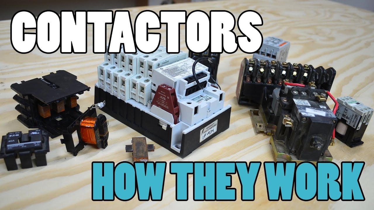
電磁接触器(コンタクタ)とは何か、そしてその仕組み by Electrician U provides neutral visual background. It does not replace the written requirements, system measurements, product documents, or safety procedure.
Evidence and safe maintenance
Before release, connect every requirement to a source or measured result. Record the operating state, current direction, command, coil behavior, auxiliary response, main-circuit current, voltage on both sides of the boundary, temperature, protection state, and permitted recovery. Define stop-work conditions for heat damage, arcing, unstable pickup, unexpected voltage, or an unverified open state. Purchasing records should preserve the complete ordering code, drawing revision, coil and suppression option, auxiliary arrangement, mounting, terminal hardware, approved alternates, and supplier document revision.
権威ある参考文献
- OSHA 1910.147 — 危険なエネルギーの制御
- OSHA 1910.333 — 電気工事の実施手順
- IEC 60947-4-1 — コンタクタおよびモータースタータ
- NIOSH — machine safety
よくある質問
What is the first step for solar battery dc contactor?
Define the exact circuit boundary and measured operating duty before selecting a product.
Is continuous current enough?
No. Check make, break, inrush, direction, fault coordination, thermal conditions, coil control, feedback, and life.
Can a similar part be substituted?
Only after the exact electrical, mechanical, insulation, control, protection, and validation evidence is approved.
How is the choice verified?
Test production-intent hardware across operating and environmental boundaries with recorded pass criteria.





