A 450V DC contactor should be selected against the highest actual voltage across the power circuit, its assigned opening and closing duty, and the installed current profile. The 450V description may refer to a maximum switching voltage rather than a nominal battery voltage. It does not identify the coil supply. For a battery system, establish the full-charge voltage and permitted operating range before reviewing a 450V-rated candidate. Then require evidence that the exact ordering code can make, carry and interrupt the intended load under those conditions.
This guide addresses a specific buying problem: deciding whether a product advertised at 450V fits a battery-fed converter or charger. It focuses on the difference between a convenient catalog filter and a documented application limit. A photograph or a large current number cannot settle that decision.
Decide whether 450V describes the source or the device
Write two separate fields in the specification: the equipment’s main-circuit operating voltage range, and the proposed contactor’s documented operating rating. A nominal pack voltage describes a reference condition. A contactor limit describes a boundary under stated conditions. Selecting by matching those two numbers can leave no allowance for the source’s normal voltage variation.
Include maximum charging voltage, permitted charger settings, and the converter’s bus behavior. Where multiple sources can feed the circuit, record which source establishes the highest voltage at each operating state. Ask the equipment designer how overshoot and other transient events are handled. Do not assume a contactor’s dielectric test voltage authorizes switching at that test voltage.
If the highest normal voltage exceeds the candidate’s supported operating range, stop that selection. A larger current variant does not repair a voltage mismatch. Likewise, an application below 450V still needs interruption, insulation and thermal review; passing one voltage check does not complete the purchase.
Read the rating conditions behind the catalog headline
Distinguish continuous carry current, making capability and breaking capability. A device may carry a load after closure yet have a different limit for opening it. The relevant breaking evidence must state DC voltage, current, circuit characteristics, direction and allowable repetition. Ask for the applicable curve or test conditions rather than accepting a single unqualified amperage.
Check whether the switching rating applies to a resistive circuit, an inductive circuit or another defined load. A battery feeding an inverter is not fully described by its steady current. The installation may contain capacitors and cables whose stored energy affects switching. Request enough documentation to compare your actual event with the stated qualification.
その IEC 60947-4-1 publication record identifies electromechanical contactor scope. Referencing that standard does not establish that a particular ordering code is certified or qualified for this circuit. Obtain product-specific evidence and use the applicable equipment requirements.
Use a purchase review table
| Review field | Equipment information | Evidence to request |
|---|---|---|
| Voltage boundary | Highest bus voltage at full charge and permitted transients | Supported operating and switching voltage, not coil or dielectric-test value |
| First closure | DC-link state and precharge completion | Making evidence for the remaining voltage difference and load |
| Opening | Current, direction and circuit condition | DC breaking limits at the actual voltage |
| Thermal installation | Current profile, enclosure and conductors | Carry rating under comparable mounting and conductor conditions |
| Control supply | Voltage at coil and driver capability | Exact coil code, pickup, holding and suppression requirements |
| 保護 | Fault source and protective response | Supported coordination with the selected protective device |
Complete the table before comparing price or delivery. A supplier can respond efficiently when each uncertainty is attached to a defined circuit condition. Mark unanswered items as open decisions rather than converting a sales description into an engineering approval.
Control capacitor charging before main closure
A discharged inverter DC link can draw a substantial transient when connected directly to a battery. The initial voltage difference, capacitance, source impedance and circuit resistance determine the event. A steady running current does not describe that first closure. Document the precharge path and the conditions permitting the main contactor to close.
Use the actual control sequence: start precharge, observe the approved completion criterion, close the main path, then place the precharge path in its intended state. The exact criterion and timing come from the equipment design. Avoid substituting a generic delay for validated completion, particularly when battery voltage or capacitor condition changes.
Specify a failed-precharge response. An automatic retry can repeatedly stress contacts if the cause remains unresolved. The educational capacitance explanation gives the physical background for stored charge. It does not supply a making rating for a selected contactor.
Review charging and discharging directions
A battery circuit can carry current toward the load and toward the battery during charging or energy recovery. Draw both paths. A polarized arc-control arrangement can require a particular terminal orientation, and its supported interruption direction must be confirmed for every assigned opening event.
Separate normal current reversal from a command to open during reversal. Some equipment opens only after the converter reduces current; another design requires interruption while current still flows. Those are different specifications. Do not describe a product as bidirectional merely because a closed contact conducts in either direction.
For a positive and negative contactor pair, also identify voltage across each open device in each state. Voltage sharing cannot be assumed equal. Use the equipment architecture and verified insulation arrangement rather than a simple division of total pack voltage.
Check the control supply independently
The coil may use a control supply entirely different from the main circuit. State its AC or DC type, nominal voltage, available range at the coil, pickup demand and holding demand. A 450V power-circuit description is not an instruction to connect 450V to the coil.
Confirm internal suppression, economizer behavior and polarity for the ordered variant. An added external suppression component can change release behavior. Include loss of control power and supply recovery in the sequence review, particularly if feedback or a separate protection device depends on timely release.
Validate heat and mounting in the actual enclosure
Use the real operating current profile and surrounding temperature. A catalog carry rating may depend on specified conductors, ambient conditions and mounting. Smaller conductors or a hotter sealed cabinet can change terminal temperature. Review both the contactor body and its electrical joints during an approved installed thermal test.
Keep heavy cable loads off the terminals. Confirm mounting orientation, fastening instructions, insulation barriers and service access from the drawing. More tightening is not a remedy for an unsupported cable arrangement. Terminal torque and permitted hardware must come from the exact product instructions.
Coordinate protection before approving a fault response
Identify the available fault current and the protective device assigned to interrupt it. A contactor used for routine connection is not automatically a fault-clearing device. Ask what it must carry, withstand or interrupt while the fuse or breaker acts. A nominal 450V label gives no answer to that coordination question.
Record commanded opening during normal operation separately from emergency or abnormal opening. Where the protection sequence first reduces current, verify how that reduction is confirmed. If a controller loses power, its intended sequence may no longer run. Review the actual resulting states instead of relying on a normal-stop diagram alone.
Send a complete RFQ and retain the approved variant
Provide the voltage range, current profile, precharge sequence, opening events, current directions, coil supply, protection and environment. Request the exact drawing revision and ordering code, plus evidence for any unresolved duty. If a substitute is proposed, compare all these fields before releasing it for installation.
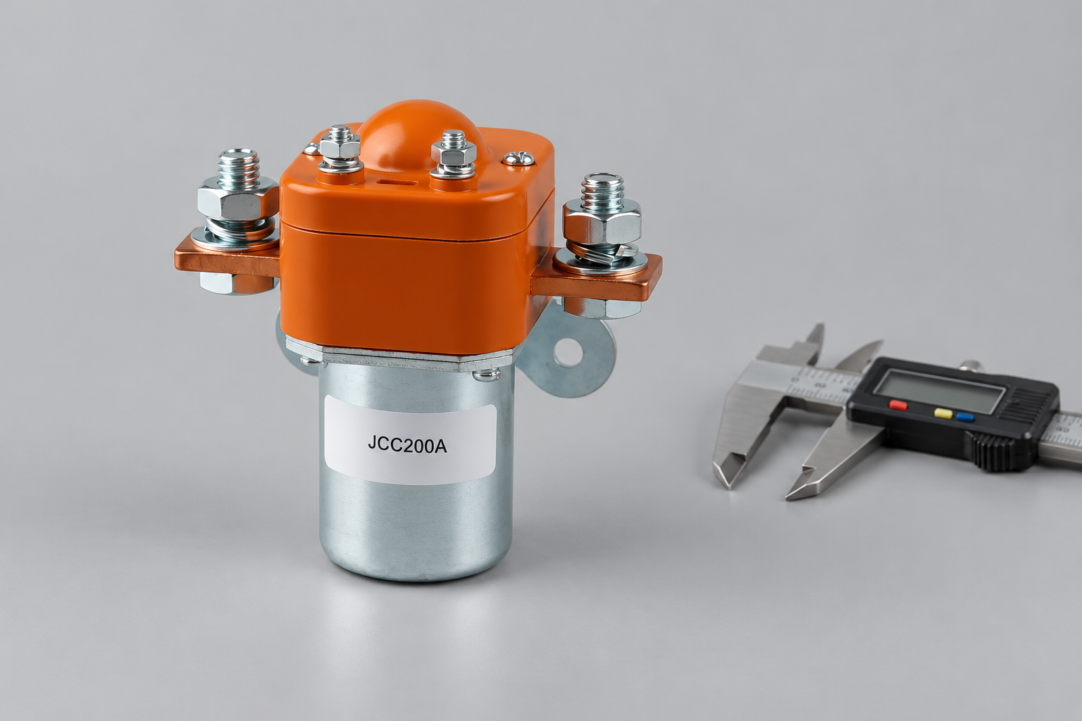
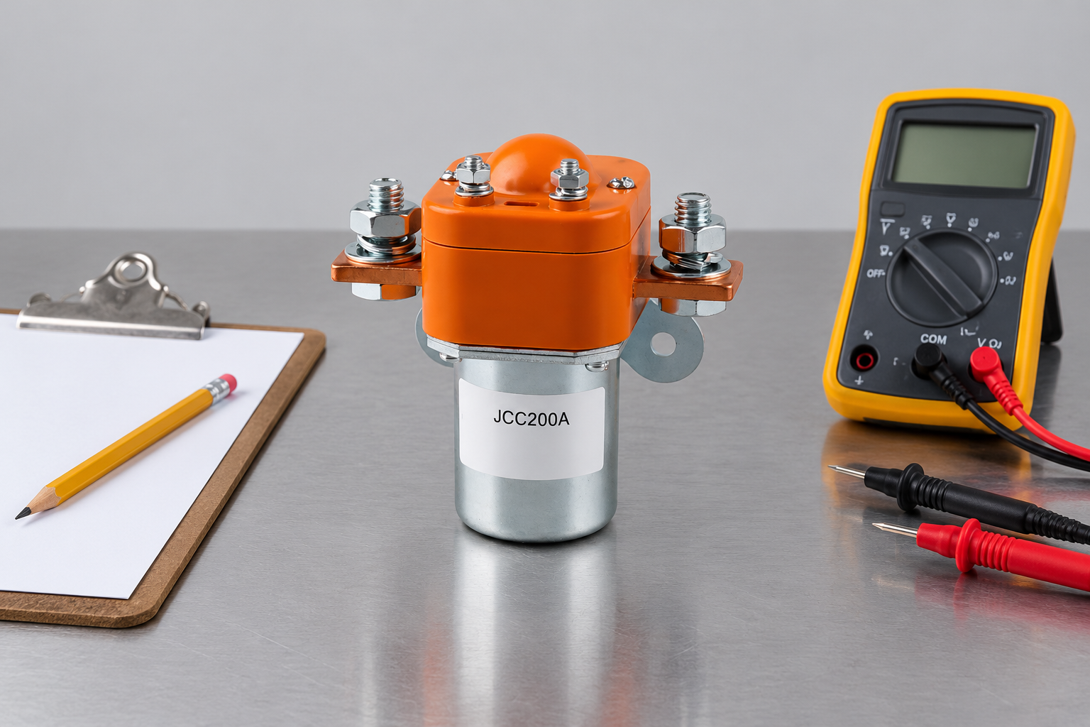
For purchasing context, Review the JCC200A Normally Open DC Contactor product page for an external construction reference. This conventional construction example is not a qualified candidate for the article’s stated duty; obtain an appropriately rated variant and product-specific evidence from Sayoon. The pictured construction is an example, not proof of a 450V application rating. Ask Sayoon to confirm the supported variant against your requirements. Use the OEM specification checklist to organize the evidence. For focused supporting checks, review precharge design, 、および DC contactor polarity.
Keep the accepted evidence with the bill of materials. Future buyers should be able to distinguish an approved replacement from a visually similar part. Record the installed verification result, not just a purchase-order description, so the decision survives changes in suppliers and personnel.
Record the acceptance decision
List each supplier document beside the application requirement it supports. Record any differences between the qualified arrangement and the proposed installation, including conductor size, mounting and control variant. The equipment reviewer should resolve those differences before the part becomes an approved replacement. A purchase record that says only 450V contactor cannot explain why one ordering code was accepted and another was rejected.
Watch the basic contactor operating principle
Electrician U explains the electromagnetic contactor mechanism in this educational video. It supports the operating principle only; it does not demonstrate the selected model’s DC ratings, qualify this application or replace product documentation.

Watch the Electrician U contactor explanation on YouTube.
よくある質問
Is 450V the coil voltage?
Not necessarily. It commonly describes a power-circuit rating in a listing. Confirm the separate coil specification and exact ordering code.
Can a nominal 450V battery use a 450V-rated contactor?
Only if the complete operating range and switching events are supported. Full-charge voltage may exceed the nominal value, so matching the nominal numbers alone is insufficient.
Does a carry-current rating prove breaking capability?
No. Require DC breaking evidence for the voltage, current, circuit characteristics and direction of the assigned opening event.
Can two contactors share the battery voltage equally?
Do not assume equal sharing. Evaluate the voltage across each device in every relevant operating and fault state using the approved circuit design.





