A 750V DC contactor must match the actual DC bus range and the switching events assigned to it. If 750V is the contactor’s maximum supported operating voltage, it cannot be treated as unlimited headroom for a nominal 750V source. For a converter-fed drive, battery system or industrial DC link, record maximum bus voltage, continuous and transient currents, regenerative operation, precharge and the stop sequence. Then select a coil variant that matches the separate control supply and verify the exact product’s DC interruption evidence.
This selection guide emphasizes converter-fed circuits. Their current and voltage depend on operating state, so a single voltage label and current headline leave important gaps. The aim is a reviewable purchasing specification with clear boundaries for routine switching, energy recovery and abnormal conditions.
Describe the bus at each operating state
List power-up, idle, normal load, peak load, regeneration and shutdown. For each state, identify the active source and the highest permitted bus voltage. A rectifier-fed bus and a battery-fed bus can have different limits, even when both are informally called 750V systems. Use the equipment’s established envelope rather than an assumed standard value.
Include the converter’s protective thresholds and any energy-management device. A brake chopper, regenerative converter or battery can influence bus behavior, but its presence does not automatically protect a contactor from every event. Document what remains functional during a supply failure or controller fault.
Also check voltage across an open contactor. A converter capacitor can retain voltage after a source is disconnected. The circuit drawing should show other sources, shared links and paths through adjacent equipment. Selection must cover the potential difference at the device, not simply the nameplate voltage of the largest source.
Assign one clear switching role
Decide whether the contactor is a routine supply connector, a commanded load interrupter or an element in a documented protective sequence. State when it closes and opens, and what current is expected at each event. Do not leave the role implicit in a controller output named main enable.
A contactor that opens after the converter has reduced current has a different duty from one required to open while a motor drive still draws load. Establish whether the current reduction is measured or merely requested. If the converter does not respond, define the resulting action and required switching evidence.
For background on the applicable equipment category, consult the IEC 60947-4-1 scope. The standard name is not a substitute for a supplier’s rating at the voltage, load conditions and repetition assigned to the selected model.
Compare candidate evidence in one table
| Review field | Equipment information | Evidence to request |
|---|---|---|
| Bus state | Normal, peak, regenerative and stopped voltages | Supported range for every assigned switching event |
| Regeneration | Reverse-current path and stop event | Permitted interruption direction and terminal orientation |
| DC-link charging | Capacitance and precharge completion | Supported making duty under the actual initial conditions |
| Repeated duty | Powered operation count and time profile | Electrical life under a comparable load |
| Coil driver | Pickup, holding, release and supply recovery | Ordered control variant and driver requirements |
| Fault response | Current reduction and clearing device | Supported coordination and abnormal-event boundaries |
This is a decision table, not a collection of generic safety margins. Fill it with the real equipment conditions and the candidate’s supported limits. Unanswered items require clarification; increasing the nominal current rating alone cannot close a missing voltage or direction qualification.
Separate conduction direction from interruption direction
Current can reverse during regeneration while the main contacts remain closed. That does not prove the device can interrupt reverse current. Review the documented arc-control arrangement, terminal orientation and supported switching directions. Request explicit evidence if the stop sequence can occur during energy recovery.
Draw the battery, converter and any external source in the regenerative state. Identify which source sustains current after an opening command and which device is supposed to absorb or interrupt the energy. A contactor should not become the unplanned solution to converter overvoltage.
Keep polarity markings visible after assembly. If the same housing is available with different internal designs, retain the ordering code and drawing revision. A replacement mounted in the same position can still have different direction requirements, so appearance and bolt pattern are insufficient checks.
Define precharge for the converter DC link
Record DC-link capacitance, initial voltage difference and the approved precharge sequence. The main contactor’s closing duty depends on what remains when it closes. A capacitor that has only partly charged can still create a demanding event. An unconditional timer can conceal changes in source voltage or a failed precharge component.
Define the completion signal, timeout response and permitted retry behavior in the equipment design. Review what happens when voltage sensing is unavailable or implausible. The capacitor charge and field explanation provides background; use circuit calculations and product evidence for actual making-duty approval.
Precharge is not a remedy for an unsupported opening rating. The main path can be well controlled at startup yet still face a difficult interruption at shutdown. Review those two events separately and keep both in the supplier request.
Check sustained current and peak duration
A converter can draw current that changes with load, input voltage and operating mode. Supply the current profile, peak duration, rest periods and enclosure temperature. A short peak and a sustained overload require different thermal evidence. Do not treat every advertised short-time current as a continuous rating.
Use conductor sizes and connection arrangements consistent with the supplier’s instructions. A busbar can remove heat differently from a cable connection, and installation details can change the result. Validate terminal and body temperatures in the actual assembly under the approved duty.
For switching-life review, count actual powered operations separately from unloaded operations. A bench test with no load can demonstrate motion and basic control response but cannot establish electrical life for the converter circuit. Set the required service life from the equipment’s operating schedule.
Match the driver to the ordered coil
Specify the coil voltage range at the terminals, pickup and holding demands, internal suppression and economizer behavior. Determine whether the controller output drives the coil directly or commands a separate driver. Confirm startup, brownout and recovery behavior for the actual supply.
Release time matters when the converter, discharge circuit or another contactor depends on the main path opening. Suppression can affect that sequence. Use the manufacturer’s documented arrangement instead of adding a diode by habit without checking existing electronics.
Review fault clearing and stored energy separately
Identify which device clears a short circuit and what the contactor must withstand before clearing. A routine supply contactor is not automatically a protective circuit breaker. Compare the available fault and protective response with documented coordination, including any requirement to remain closed or open during the event.
For covered electrical servicing, OSHA 1910.333 addresses de-energization and verification. Opening the controller’s main contactor does not establish that a charged DC link, parallel source or all accessible parts are safe to touch. Qualified procedures must account for stored energy and other feeds.
Release the purchase only after duty approval
Send the supplier an operating-state diagram, bus limits, current profile, precharge criteria, opening events, direction requirements, coil details and installation conditions. Ask for explicit limits and supported ordering codes. A useful response identifies both supported duty and unresolved questions instead of repeating the headline rating.
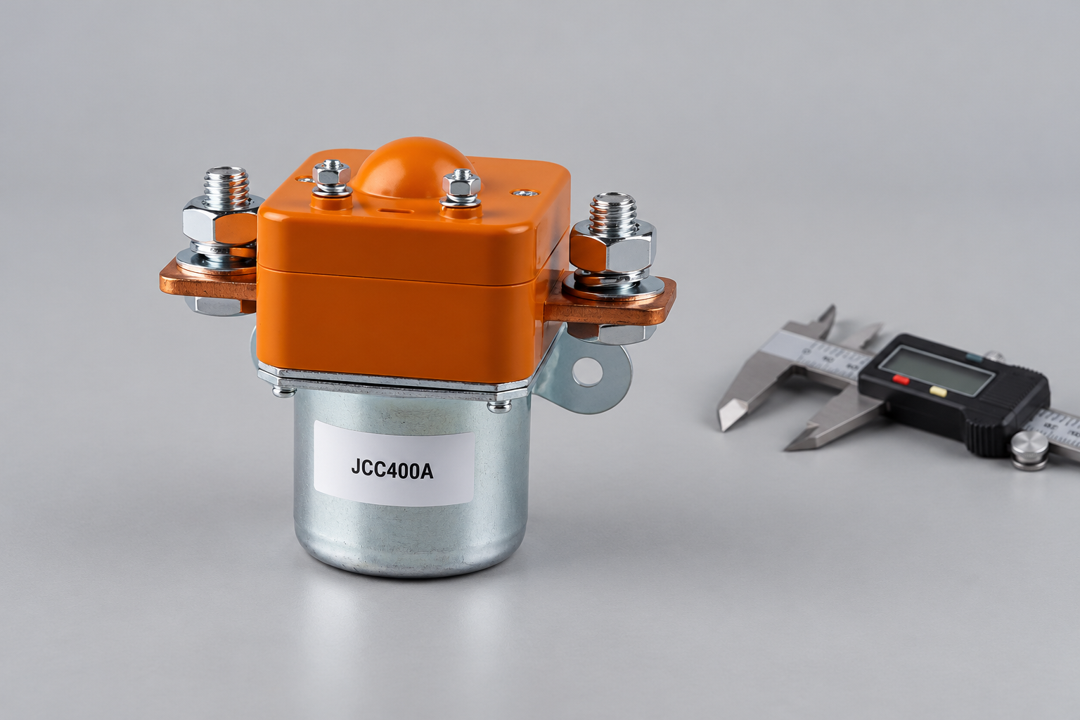
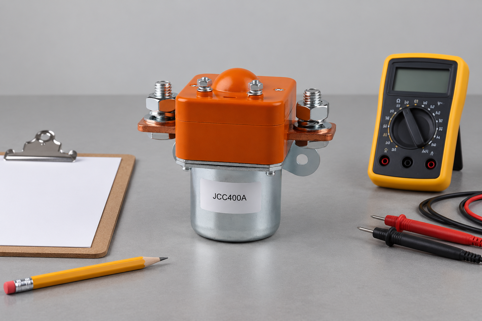
Review the JCC400A Normally Open DC Contactor product page for an external construction reference. This conventional construction example is not a qualified candidate for the article’s stated duty; obtain an appropriately rated variant and product-specific evidence from Sayoon. The illustration identifies construction, not a guaranteed 750V application match. Use the OEM specification checklist to organize the evidence. For focused supporting checks, review regenerative current review, 그리고 powered switching-life assessment. Keep the approved switching evidence and installation result with the replacement specification so a future substitute receives the same review.
Retain the drive operating sequence with the order
A supplier cannot assess regeneration from a one-line request saying 750V drive. Include a state diagram showing when the converter is active, when current reverses, when precharge occurs and when each contactor changes state. Record which signals confirm readiness and which are only commands. If the software sequence changes later, check whether the accepted switching duty still describes the new event. Keep that revision with the electrical drawing and ordering code.
For a replacement, compare the original and proposed coil behavior, release timing and polarity instructions. An unchanged bolt pattern does not show that the drive will stop or restart in the same way.
Watch the basic contactor operating principle
Electrician U explains the electromagnetic contactor mechanism in this educational video. It supports the operating principle only; it does not demonstrate the selected model’s DC ratings, qualify this application or replace product documentation.

Watch the Electrician U contactor explanation on YouTube.
자주 묻는 질문
Can a 750V DC contactor interrupt regenerative current?
Only when the exact product supports the assigned interruption direction and conditions. Conducting reverse current while closed is not enough evidence.
Does a converter stop command remove contactor load immediately?
Not necessarily. Verify the converter response and actual current reduction before relying on it in an opening sequence.
Is precharge still needed with a high current contactor?
Evaluate the capacitor charging event independently. A large carry-current rating does not establish safe making duty into an uncharged DC link.
Does an open contactor make the DC link safe to service?
No. Stored energy and other sources must be addressed by the applicable isolation and verification procedure.





