빠른 답변: The most useful weld check is a de-energized-state plausibility test: command the contactor open, confirm its auxiliary indication, remove the expected source, and measure whether the load-side bus decays to the documented threshold. A voltage that remains near pack potential is evidence of a welded, bypassed, or back-fed path. Do not close another contactor or retry repeatedly until the stored energy and fault path are understood.
Reliable ev contactor weld detection compares what the controller commanded with what the high-voltage circuit actually did. A welded contactor can leave a battery connected after an open command, while a stuck-open device can look similar if the test checks only one signal. The best diagnostic combines auxiliary feedback, bus-voltage measurements, timing, isolation status, and a controlled precharge or discharge sequence.
At-a-glance design map
| Element | What it does | Selection or diagnostic focus |
|---|---|---|
| Auxiliary plausibility | Compare commanded and reported mechanism state | Fast but cannot prove low-resistance main contacts |
| Bus-voltage decay | Measure load-side voltage after opening | Detects welded or back-fed path; needs a defined discharge path |
| Precharge comparison | Compare expected rise with measured rise | Separates stuck-open, wrong wiring, and abnormal capacitance |
| Isolation monitor | Check pack-to-chassis insulation state | Adds system context; not a direct weld measurement |
Product reference and scope
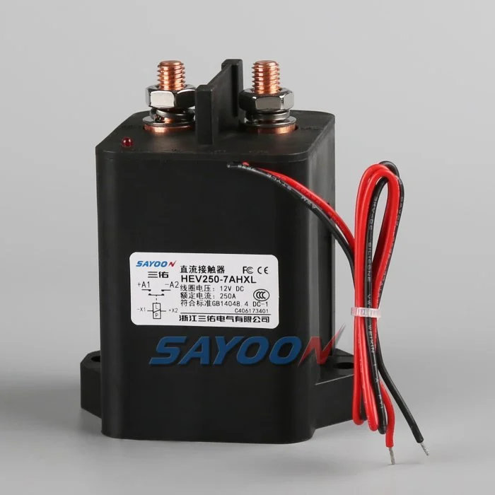
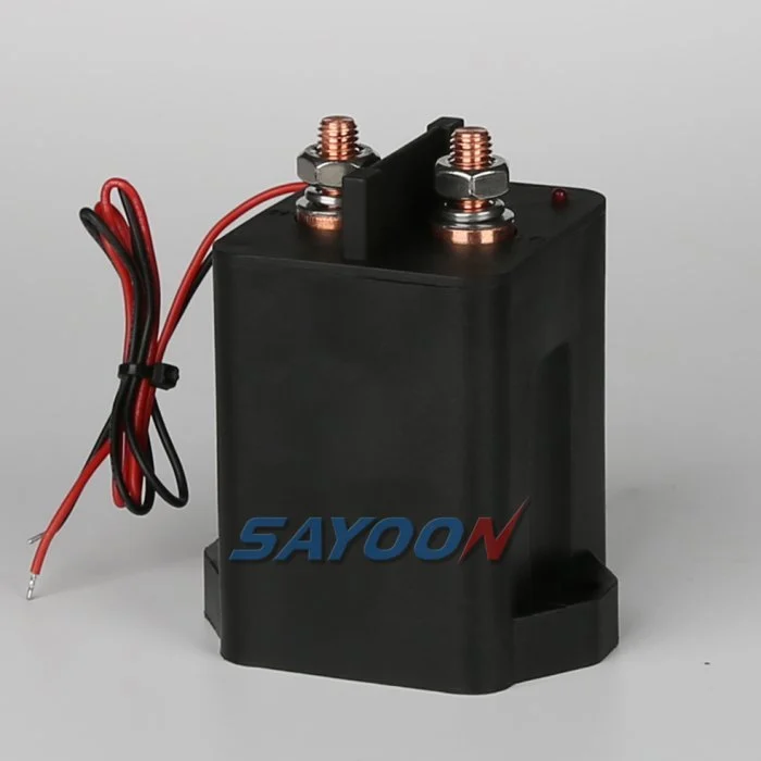
The HEV250 high-voltage sealed DC contactor shown in this article is a real Sayoon product reference. See the HEV250 high-voltage sealed DC contactor product page 그리고 고전압 DC 접촉기 범위 for the family context. The image does not replace a model-specific drawing review; voltage, coil, current, insulation, duty, and mounting must be confirmed for the application.
What a weld means electrically
A contact weld is a main-contact failure in which the device does not separate after current interruption. It can follow excessive make current, short-circuit energy, repeated capacitive inrush, poor coordination, contamination, or a mechanical problem that holds the armature. The visible command may turn off while the battery remains connected. In an EV, that is a safety and service problem because the inverter, charger, and exposed harness may still be energized.
A weld is not the only explanation for a high load-side voltage. A precharge resistor, charger, DC-DC converter, insulation monitor, or an unintended wiring bridge can back-feed a bus. The diagnostic must therefore identify the measurement point, wait for the known discharge time, and compare the result with an approved model of the circuit.
Use the command and feedback as a pair
Record the coil command, coil current, auxiliary contact state, pack voltage, load-side voltage, and time base on the same capture. If the controller says “open” but the auxiliary remains closed, the mechanism may be stuck or the auxiliary circuit may be miswired. If the auxiliary opens but the load-side bus does not decay, suspect welded main contacts or a back-feed. If the voltage drops normally but the auxiliary disagrees, inspect the feedback device and connector.
Auxiliary feedback is a diagnostic input, not a safety proof by itself. Contact bounce, debounce logic, a broken wire, or a contact rating exceeded by the input circuit can create a false state. Apply a plausibility window rather than a single sample and retain the first mismatch as the fault record.
Precharge and discharge tests
A precharge test is useful before closing the main path: the load-side bus should rise through the resistor with a predictable time constant. A stuck-open main contactor may never reach the close threshold; a welded device can make the bus rise too quickly when the precharge path is not the only path. After an open command, the discharge test asks the inverse question: does the load-side voltage fall through the approved resistance and reach the safe threshold?
The capacitance, resistor, leakage, and measurement divider all affect the curve. Do not use a universal timeout. Capture at least the starting voltage, final voltage, slope or time constant, temperature, and the state of every other connected converter.
Isolated voltage sensing
Texas Instruments describes an isolated-switch approach that uses a voltage divider and isolation to detect welded and stuck-open relays in EV architectures. The design principle is more important than copying a component: keep the high-voltage measurement isolated, limit fault energy, and choose thresholds that tolerate divider error and transient noise. Place the sense point so a downstream converter cannot hide a welded main contact.
A divider that is too high impedance can be disturbed by leakage and EMC; one that is too low increases continuous loss and fault energy. Protect the measurement input, validate creepage and clearance, and test open-wire and short-to-ground cases.
Timing and threshold design
Weld detection should state when sampling begins, how long the discharge is allowed to run, what voltage threshold is safe, and what the controller does if the threshold is not reached. Thresholds should include measurement tolerance, ADC resolution, temperature, and the pack voltage range. A fixed “under 60 V” rule may not match the equipment risk assessment or the service boundary.
Measure the complete response at cold and warm conditions and after repeated switching. A contactor that passes once can fail after contact heating. Use a monotonically increasing fault counter or latched event rather than clearing the record after a later successful cycle.
Distinguish weld, stuck-open and back-feed faults
A welded contactor generally leaves voltage present after an open command and may show closed auxiliary feedback. A stuck-open contactor usually leaves the load-side bus low during a close command while the source remains healthy. A back-feed can leave voltage present even with both main devices open, but its source may be limited and collapse when an upstream converter is disabled. These signatures overlap, so the test should isolate branches in a controlled order.
Never diagnose by shorting around a fuse or manually forcing a contactor in an energized pack. The safe contactor test workflow should be followed by an authorized technician with lockout, appropriate probes, and a documented discharge check.
Specify a contactor to reduce weld risk
Detection is the last layer; correct specification reduces the probability. Provide the maximum DC voltage, continuous and make current, capacitive inrush, fault-clearing time, current direction, precharge profile, switching cycles, enclosure temperature, vibration, coil supply, suppression, and short-circuit coordination. Confirm that the selected contactor is approved for the actual breaking duty, not just the nominal steady current.
The HEV250 image is a product reference. A Sayoon engineering review should compare the complete waveform and installation against the candidate data sheet, then define an acceptance test for make, break, precharge, and welded-state diagnosis.
Field service decision tree
If the load bus remains high, stop automatic retries, isolate the pack according to the service procedure, verify absence of voltage with a suitable instrument, and record the contactor and harness identity. Check for an external source before condemning the device. If a weld is confirmed, replace the contactor and inspect the fuse, precharge resistor, bus capacitor, and control timing that may have caused it. Prove the discharge and feedback tests before returning the vehicle.
This evidence also helps a manufacturer improve the design. Include the fault time, current trace, temperature, number of cycles, software state, and any recent wiring or firmware change in the report.
Acceptance record for the engineering team
Before approving this ev contactor weld detection decision, create one controlled record that can be read by the design engineer, test engineer, production team, and service technician. List the exact part number and coil option, drawing revision, terminal labels, bus voltage range, current waveform or duty profile, ambient and enclosure temperatures, mounting orientation, conductor size, terminal torque, driver and suppression details, auxiliary logic, HVIL state, measurement instruments, calibration dates, and the pass/fail thresholds. Separate catalogue values from measured values and identify every assumption. If a value is not available, mark it as an open engineering action instead of filling the gap with a typical number.
Run the sequence at the boundaries that matter: minimum and maximum low-voltage supply, cold and warm equipment, the longest approved harness, repeated cycles, and the abnormal state that the safety concept names. Capture command, coil current, feedback, pack voltage, load-side voltage, and fault flags on one time base. After a failed event, stop automatic retries, isolate stored energy, and preserve the first-fault data. A later successful cycle does not erase evidence of a welded contact, slow release, intermittent interlock, or driver protection event. Release the product only when the complete record is reviewed against the current data sheet and vehicle-level requirements. Include photographs of the terminal layout and probe locations, the software build and calibration state, and a short explanation of why the chosen threshold is safe. This makes the result repeatable when a replacement sample, new harness, or firmware revision is introduced.
Related engineering guidance
사용하세요 직류(DC) 접촉기 선정 가이드 for the broader sizing workflow, the safe contactor test guide for isolation and measurement, and the 오픈 및 폐업 시간 안내 when setting diagnostic windows. For PLC-connected control logic, see the PLC 코일 제어 가이드. These internal links support the decision without replacing the device data sheet or the vehicle safety procedure.
교육용 비디오
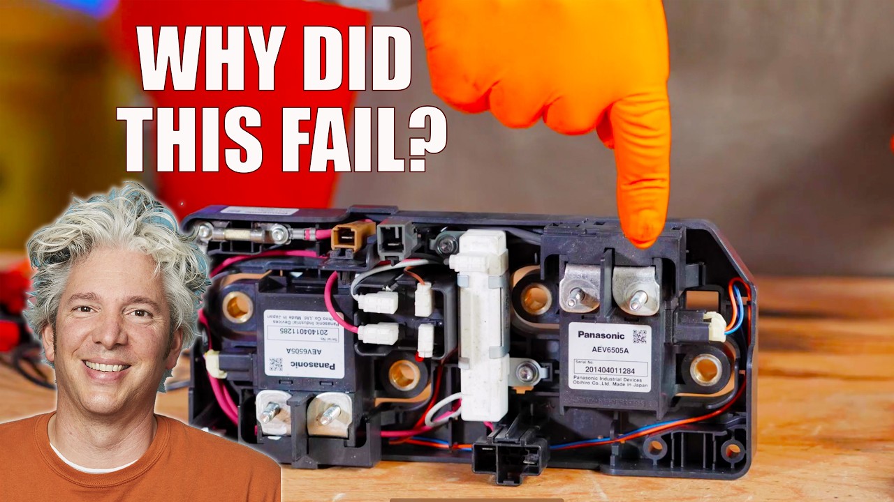
This neutral training video is included for visual context. It is not a product endorsement and the written, model-specific requirements above control the engineering decision.
자주 묻는 질문
What is the first check for ev contactor weld detection?
Confirm the exact command, supply, coil option, and safe measurement points before energizing anything. Then compare the expected feedback and bus-voltage response with the approved sequence.
Can auxiliary feedback prove the main contacts are healthy?
No. It reports mechanism position within its own limits. Combine it with load-side voltage, timing, and the documented circuit state.
Can I use a generic contactor driver or suppression diode?
Only after the coil, driver, polarity, release time, EMC, and protection behavior are approved together. A generic change can create slow release or false diagnostics.
견적요청서(RFQ)에는 무엇이 포함되어야 합니까?
Provide voltage, current waveform, switching duty, temperature, mounting, coil voltage, suppression, feedback, insulation, life, and the required drawings and test evidence.
Sources and standards context
- Texas Instruments relay-welding detection application note
- Sensata contact-welding application note
- Google Patents contactor weld-detection method
Standards, safety rules, and supplier ratings change by market and product revision. Use the current edition adopted by the project and obtain the full requirements through the responsible engineering and compliance process.





