Contactor coil cable voltage drop can make a correctly specified DC contactor fail to close when the control run is long, a conductor is undersized, or multiple devices share a return. The useful number is not the unloaded voltage printed on the power supply: it is the loaded voltage measured across the coil terminals during pickup. Estimate the round-trip conductor loss, then include the driver, connector and source losses and confirm the result with an actual test. There is no universal maximum cable length. The permissible length depends on the exact coil’s pickup requirement, current waveform, supply envelope, wire material and cross-section, temperature, and control topology.
Follow both conductors, not just the outbound cable
A DC coil needs a complete current loop. Current leaves the source, passes through protection and a driver or relay contact, travels down the outbound conductor, enters the coil, then returns through another conductor and the source return. Both long conductors contribute resistance unless the actual circuit differs. A 30 m physical distance with a separate supply and return is roughly 60 m of copper path before connection leads. Treating 30 m as the entire electrical length would understate conductor loss by about half in this simple two-wire layout.
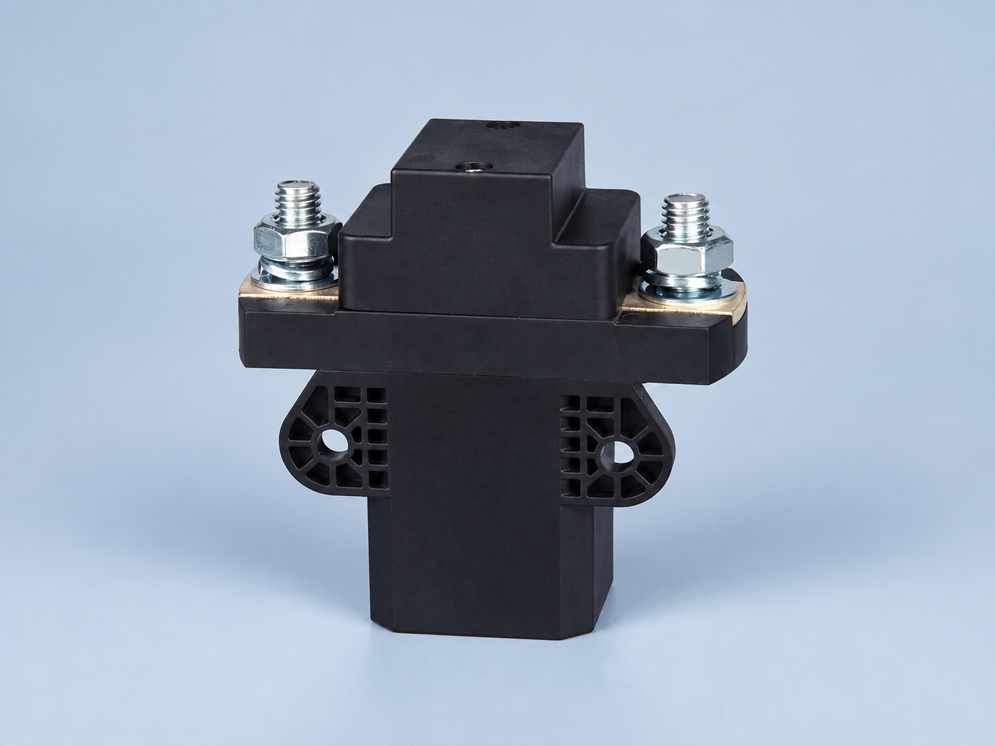
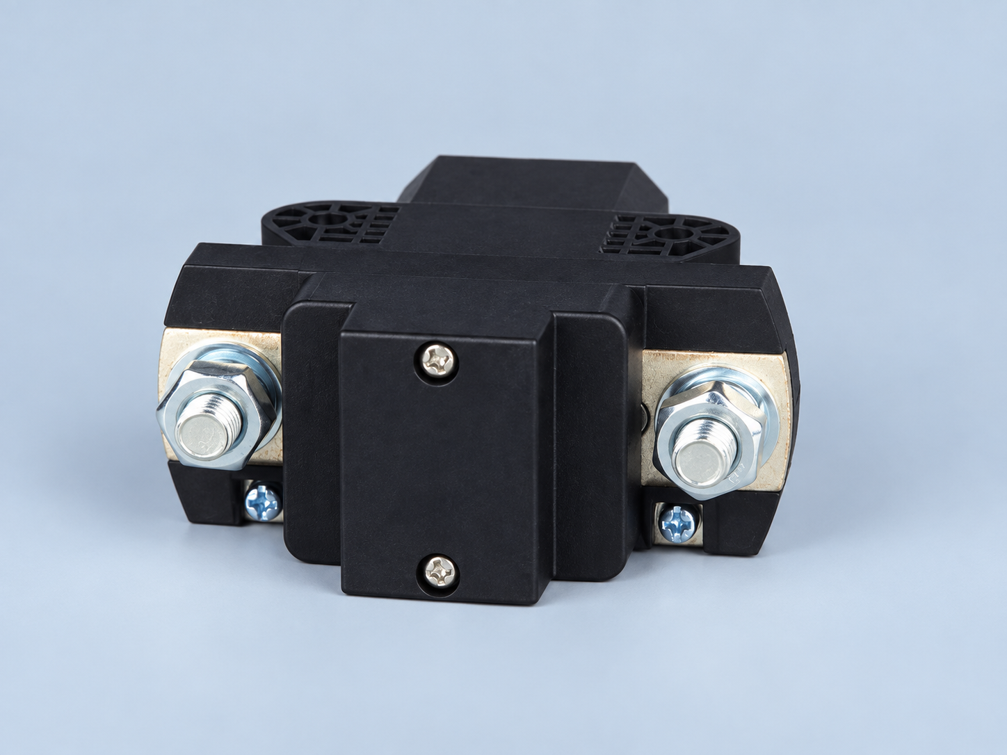
The coil terminals and the main power studs must never be confused. The voltage drop discussed here is in the control circuit, not the voltage drop across the contactor’s closed main contacts. The control drawing—not the photograph alone—identifies coil leads, polarity, economizer and any internal suppressor. A QZJ-series contactor may show prominent high-current studs, yet those studs are not the measurement points for coil voltage. Verify the selected option’s terminal map before energizing or testing it.
Many search results discuss AC contactors or loose main contacts. Those are different diagnoses. For the coil-run question, use DC conductor resistance at operating temperature, actual pickup current and the minimum loaded control-source voltage. Also consider wiring in parallel with noisy power conductors, grounding and the location of the suppression device. Noise and a voltage deficit may coexist, but the remedies differ. A simple conductor upsizing does not automatically solve a supply that current-limits during pickup.
Calculate a first-pass loop loss
For a two-wire copper control run, the preliminary conductor-only loss is ΔVcable = I코일 × (Rout + Rreturn). With identical conductors, that becomes I × 2Lr, where L is one-way distance and r is conductor resistance per unit length at the relevant temperature. Use the actual cable datasheet or recognized conductor data and adjust for hot operation; copper resistance rises as it warms. Add the loss of terminals, plugs, relays, output devices and any shared wiring separately. A poor crimp is not captured by the ideal cable calculation.
Here is an intentionally illustrative arithmetic example, not a Sayoon rating or cable recommendation. Assume a 24 V control supply delivers 23.2 V under pickup load, a 40 m one-way run uses a conductor listed at 0.018 Ω/m at the assessed temperature, pickup current is 1.0 A, and the driver plus connections lose 0.6 V. Round-trip conductor resistance is 2 × 40 × 0.018 = 1.44 Ω; conductor loss is 1.44 V. Estimated coil voltage is 23.2 − 1.44 − 0.6 = 21.16 V. Whether that is acceptable can be decided only against the exact ordered coil’s stated pickup range and the verified source/current values. Substituting a lower hold current would hide the worst pickup loss.
Do not infer coil current by dividing nominal voltage by a cold resistance unless the chosen device truly behaves like a simple fixed winding over the interval of interest. Some coils have electronics or an economizer, and the current waveform can change after armature closure. Measure or obtain both pickup and hold requirements. Also check what happens if another contactor pulls in simultaneously on the same supply. The minimum source voltage for that combined event may be lower than either single-device test suggests. Our coil power and driver sizing article addresses that separate current-budget problem.
| Loss or condition | How to estimate | How to verify on the machine | Typical missed detail |
|---|---|---|---|
| Outbound and return copper | Current times total hot loop resistance | Measure source and coil voltage during pickup | Counting only one-way cable distance |
| PLC or driver output | Datasheet on-state drop at coil current | Probe input and output under the same load | Using a zero-current logic reading |
| Connectors and relay contacts | Account for approved ratings and condition | Measure differential drop while loaded | Hidden resistance from a damaged termination |
| Supply and shared return | Use worst simultaneous control load | Record loaded source and return potentials | Other loads starting at the same time |
| Temperature and duty | Use conductor and coil data for intended range | Repeat at representative hot and cold states | Commissioning only at room temperature |
Pickup is usually the decisive measurement window
A long run may show a respectable voltage with the coil de-energized because the meter draws almost no current. As soon as the coil is commanded on, current produces voltage drops across the loop. The minimum may occur just as the device begins to pick up, especially if the control source or output stage sags. A slow digital multimeter can average across that dip. Use a suitable recorder or oscilloscope with safe isolation and time resolution when a transient matters. Keep the source voltage and coil voltage on the same time base if possible.
Measure at the actual coil leads or terminals, not only at the control-cabinet output. If the source stays stable while the coil sags, the difference points to the wiring/driver path. If both sag together, the supply or a shared feed is implicated. Compare the forward and return sides while current flows to localize loss, following the equipment’s safety procedure. A repeated chatter event can damage contacts; Schneider Electric warns that insufficient control voltage can produce unstable holding and contact wear. Its discussion is general guidance, not a voltage threshold for a Sayoon model.
At hold, measure again after the contactor and enclosure warm up. The coil may draw less current after an economizer activates, so a hold-voltage measurement can appear healthy even though pickup was marginal. Conversely, a poorly ventilated hot cabinet may increase cable resistance and expose a marginal design. A controller output may have its own thermal derating. ABB’s contactor troubleshooting guidance also links low control voltage and supply disturbances to unreliable operation. Use it to frame diagnostic checks, not to assign its percentage limits to the product pictured here.
Size the control path for the worst plausible event
Start with the required terminal-voltage window from the coil manufacturer. Determine source minimum and maximum while loaded, including power conversion, battery state or control-transformer regulation as applicable. Calculate the allowable voltage loss as the difference between the minimum source voltage and the minimum permitted coil-terminal voltage after reserving margin for driver and connections. Then select conductor size and architecture for the intended length and ambient range. If the documentation lacks a reliable pickup requirement, ask the manufacturer instead of selecting cable from an arbitrary percentage rule.
For multiple coils, check simultaneous starts and any shared outbound feed or return. Shared segments carry the combined current, so their voltage loss is not equal to that of one branch. Consider moving the local control supply closer to the contactor or using an approved remote driver when a long run would otherwise exceed the loss budget. A relay placed at the far end still needs its own correctly powered coil, and a changed topology introduces new fault and protection questions. Wire gauge alone cannot fix an output transistor with excessive on-state drop or an underpowered source.
Review polarity and suppression before changing connections. A DC coil with a built-in diode or electronic driver may be polarity-sensitive. Moving a suppressor can change the high-frequency transient loop and release dynamics. If the application requires a defined release time, check the complete device with the chosen protection; see our flyback suppression and release timing guide. A cable loss investigation is also a control reliability investigation: a voltage deficit can cause closure delay, repeated partial closure or unexplained restart behavior.
Commissioning checklist and purchasing handoff
- Record exact contactor and coil option, supply, driver, cable construction, one-way run and shared return segments.
- Obtain the coil pickup, hold and dropout data for the specified temperature and duty; keep main-contact data separate.
- Calculate hot round-trip cable resistance using the actual conductor; include driver and connection losses.
- Check source voltage and coil-terminal voltage simultaneously during cold start and the largest credible simultaneous control load.
- Repeat at hot enclosure conditions after thermal stabilization, capturing both pickup and hold.
- Inspect and measure suspicious terminations; compare forward and return path drops while loaded.
- Verify chatter, feedback and release behavior under the defined low-voltage and power-restoration scenarios.
- Retain drawings, waveforms, temperature, instrument information and replacement-cable specification in the commissioning record.
For a real hardware starting point, see the Sayoon QZJ200A product page. The photo shows the actual housing used in this article, but it does not substitute for the coil-option data and terminal drawing. Send the vendor the one-way length, conductor size, shared segment, minimum source voltage during pickup, driver type, measured coil voltage and operating temperature. Ask for explicit confirmation of the exact option in this control architecture. The broader 직류(DC) 접촉기 선정 가이드 helps align the main-power and coil decisions without mixing their ratings.
Video: measuring voltage at a contactor
This independent multimeter demonstration illustrates the idea of checking voltage at a contactor. It is not a Sayoon wiring diagram, and long-run pickup sag may require a faster, appropriately isolated instrument.
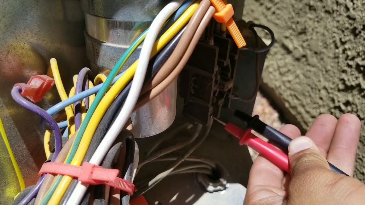
Watch the voltage-measurement demonstration on YouTube.
자주 묻는 질문
Should I count one-way or round-trip cable length?
Count the resistance of the complete current loop. With separate equal outbound and return conductors, the copper path is approximately twice the one-way distance, plus connection leads.
Why does the coil show full voltage when off but fail during pickup?
With almost no current, the cable and driver develop little voltage loss. Pickup current reveals the loaded drop, so record voltage at the coil during the actual command.
Can a hold-voltage reading prove that the cable is large enough?
No. Pickup current and supply sag may differ from hold, especially with an economizer. Check the exact coil’s pickup range and capture the closing interval.
Is there a standard maximum distance for a 24 V DC contactor coil?
No universal distance applies. It depends on source minimum, coil pickup requirement, current, conductor resistance and temperature, driver loss and shared loads.





