Contactor coil current measurement must separate the short pull-in event from the stabilized hold condition. Measure current in one coil conductor while recording voltage directly across the coil and the contactor’s mechanical or auxiliary-contact response on the same time base. A handheld meter’s steady reading can describe hold current but may miss the pull-in peak, an economizer transition, supply sag, or chatter. Use an instrument with adequate DC bandwidth, range, isolation, and transient capture for the exact coil. Never infer a universal current value from housing size, main-contact rating, or a different coil option.
Define pull-in and hold before selecting an instrument
Pull-in begins when the coil is energized and ends only after the moving system reaches its intended closed position. Hold is the later condition in which the contactor remains closed. A conventional winding, an electronic wide-range coil, and an economized coil can produce very different waveforms. Some designs draw a distinct initial pulse and then reduce current; others change more gradually as resistance and magnetic position change. Obtain the exact order code, coil voltage, polarity, internal suppression, economizer details, permissible duty, and manufacturer test conditions before interpreting a trace.
The main current through the power contacts is a separate circuit. Clamp only one control conductor for coil current. Enclosing supply and return together makes their magnetic fields cancel and can produce a misleading near-zero reading. If an inline shunt is used, confirm its resistance, power, common-mode rating, bandwidth and effect on coil voltage. A shunt that steals significant voltage can create the very pickup fault being investigated.
Capture current, coil voltage, and state together
A current trace alone cannot show whether the coil received enough voltage or whether the armature completed its travel. Record coil-terminal voltage, coil current, driver command, and an appropriate position or auxiliary signal with synchronized timing. Where the application permits, a mechanically observed closure or calibrated motion sensor can supplement the auxiliary contact. Keep probes and reference points within their voltage and safety ratings. A software command is not an energy-isolating device for the main DC circuit.
For a clamp measurement, zero the DC probe away from strong magnetic fields, select a range that resolves hold current without clipping pickup, and place the conductor consistently within the jaw. Fluke explains that inrush capture requires a meter designed for the short starting event. Its motor example is not a Sayoon coil specification, but the measurement principle applies: an ordinary display update can miss a transient. Fluke’s clamp-accessory guidance also emphasizes selecting the correct AC/DC probe and range.
| Measurement | Purpose | Common error | 기록 |
|---|---|---|---|
| Pull-in current | Size source and driver; detect abnormal closure | Meter too slow or range clipping | Peak, duration, trigger and waveform |
| Hold current | Continuous loading and thermal input | Reading before economizer settles | Mean, ripple, temperature and voltage |
| 코일 전압 | Separate coil behavior from wiring loss | Measuring only at supply | Minimum during pickup and steady value |
| State timing | Relate current changes to closure | Assuming command equals motion | Command, feedback and contact timing |
| Release transient | Check driver and suppression stress | Unsafe reference or insufficient bandwidth | Peak voltage and current-decay time |
Use a repeatable test sequence
- Verify exact contactor, coil option, wiring drawing, supply range, suppressor and driver.
- Isolate hazardous main-circuit energy under the approved procedure; decide whether the control circuit can be tested separately.
- Connect voltage and current instruments with documented ranges, calibration and isolation.
- Capture several cold pull-ins at the minimum intended loaded supply, not below an approved limit.
- Repeat at nominal and maximum intended supply, recording closure and feedback timing.
- Allow the coil to reach the required thermal condition and record stabilized hold current.
- Repeat with simultaneous control loads and the installed cable to expose source or harness loss.
- Save raw traces, temperatures, probe settings, firmware, drawing revision and pass criteria.
Do not average away failed operations. Report distributions and any chatter, delayed closure, economizer transition failure or inconsistent feedback. Compare results only to the exact product documentation or an approved engineering specification. For supply compatibility, use our coil power guide 그리고 PLC driver guide; neither provides a substitute current limit.
Interpret the waveform without inventing limits
A higher-than-expected initial current may reflect supply voltage, coil temperature, probe offset, an electronic input stage or a mechanical condition. A low current may reflect voltage drop, current limiting, open resistance or the wrong coil. If current persists in a supposed pull-in mode, check whether the mechanism fully closes and whether an economizer changes state. If current is normal but motion is slow, investigate mechanical and main-system conditions rather than raising voltage beyond the specified range.
Coil resistance changes with temperature, so cold and hot current should not be compared without temperature and voltage. For an electronic coil, simple resistance arithmetic may not describe input behavior. Measure rather than assume. Link the current trace to the opening and closing time method, and preserve model-specific boundaries in the report.
Convert results into selection and commissioning evidence
Driver selection must cover the measured or specified pickup event, continuous hold duty, supply tolerance, switching frequency and turn-off transient with margin defined by the project. Check per-point and group limits for a PLC output, relay DC-inductive duty, conductor voltage loss and power-supply current limiting. A bench supply with short leads may hide a field harness problem. Conversely, long test leads and an intrusive shunt can create an artificial problem.
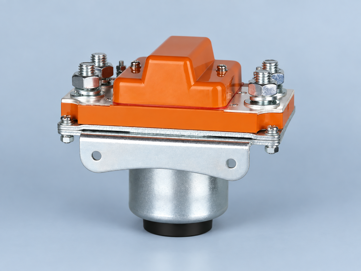
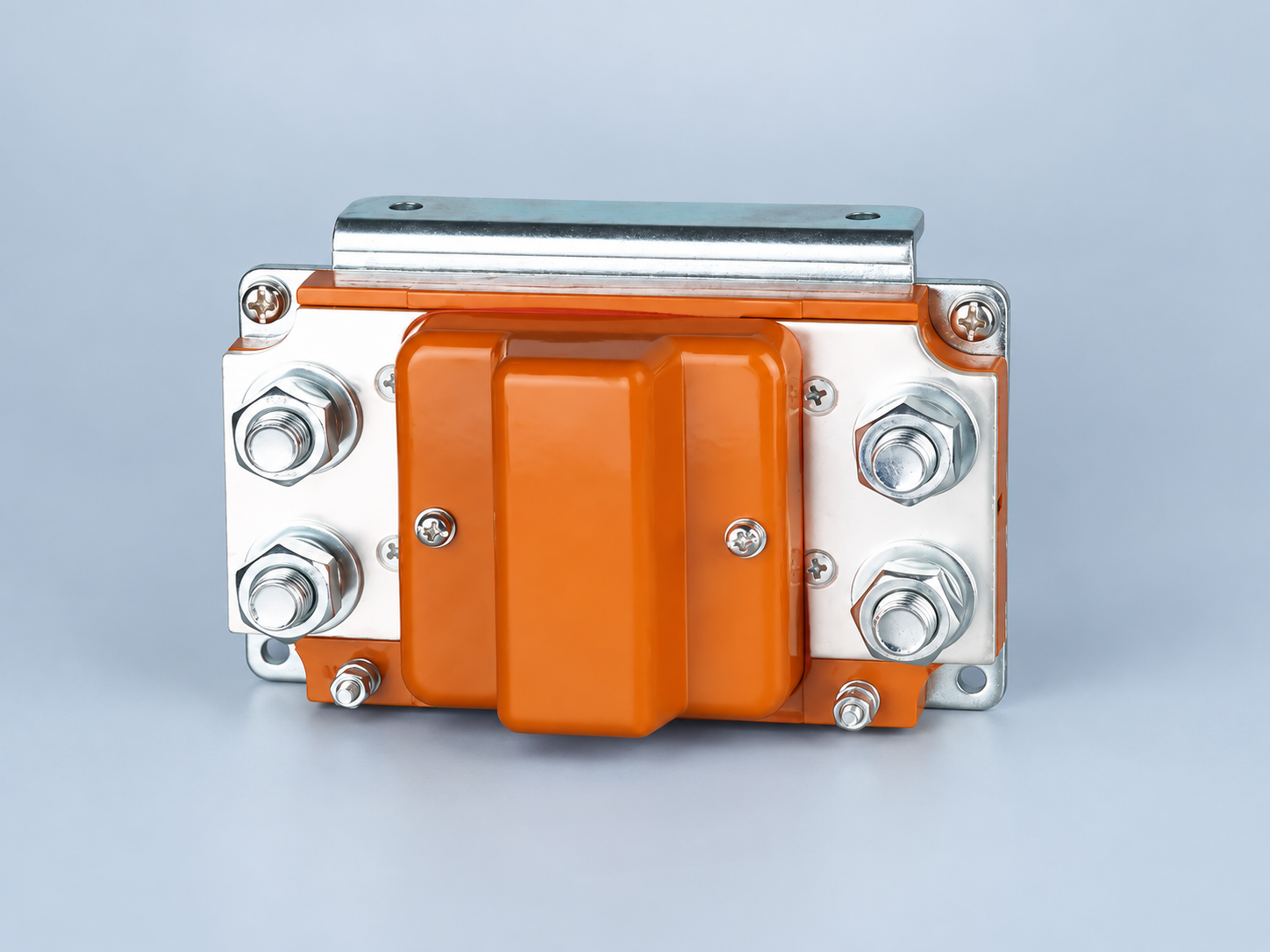
그 Sayoon SZJ1000A product page is the real image reference for this article. Request coil-current requirements for the exact option rather than reading the 1000 A main rating as a control value. Start broader selection with the 직류(DC) 접촉기 선정 가이드 and apply the safe test boundaries before commissioning.
Diagnose common trace patterns
A trace that rises and immediately collapses before feedback changes can indicate current limiting, driver shutdown, an open connection, or a supply that cannot support pickup. Current that remains elevated while the contactor chatters calls for simultaneous inspection of coil voltage and mechanism state. A clean electrical waveform with inconsistent feedback points toward the auxiliary circuit, timing setup, or linkage rather than the supply alone. These patterns narrow the next safe check but are not diagnoses by themselves.
When comparing units, keep voltage, ambient, coil option, suppressor, probe location and trigger identical. Preserve raw traces and failures, not only the cleanest capture. For PWM control, report duty cycle, frequency, ripple and measurement bandwidth because a meter average can hide peak stress.
Prepare a useful RFQ and acceptance record
Send the supplier the coil supply range, driver, cable length, switching frequency, energization time, suppression, temperature and measured traces. Ask for pickup and hold demand, permitted waveform, voltage tolerance, thermal duty and release behavior for the exact option. Define whether acceptance uses peak current, pulse duration, average hold current, temperature rise, closure time, or all of them.
Record the instrument, probe, zero method, sample rate, bandwidth, range, uncertainty, orientation and calibration. Include actual coil-terminal voltage and a sketch showing which single conductor passed through the clamp. Repeat enough cycles to reveal variation and log the thermal condition for each series.
최종 설계 검토 및 증거 패키지
릴리스 전에 원래 설계자가 아닌 다른 사람에게 현장 상태의 배선을 승인된 도면과 정확한 제품 문서와 비교해 보십시오. 단자 식별, 도체 배선, 토크 증거, 보호, 코일 공급, 차단, 접점 상태 및 컨트롤러 설정을 확인하십시오. 모든 명시된 승인 한계가 추적 가능한 원천을 가지고 있으며, 설명적인 예가 비공식적인 제품 등급으로 전환되지 않았는지 확인하십시오. 사진은 설치를 확인할 수 있도록 도와주지만, 도면, 측정값 또는 제조업체의 확인을 대체하지 않습니다.
예정된 저온 및 고온 제어 공급 조건과 관련 있는 저온 및 고온 상태에서 반복적인 작동을 수행합니다. 동시 제어 부하, 현실적인 케이블, 인클로저 구성 및 예상되는 전환 순서를 포함하세요. 재설정 없이 예기치 못한 동작을 기록하고 버리세요. 필수 제품 값이 계속해서 사용 불가능한 경우, 해당 항목을 엔지니어링 검토 항목으로 표시하고 다른 접점과 유사한 방식으로 해당 기능을 승인하지 마십시오.
마지막 패키지를 구매 및 유지 관리와 제어 엔지니어링에 전달합니다. 이 문서에는 주문번호, 승인된 대체품, 도면 수정 사항, 테스트 설정, 원시 측정값, 통과 기준, 편차, 소프트웨어 버전, 보호 장치 식별 정보 및 교체 지침이 모두 포함되어야 합니다. 이는 시각적으로 유사한 코일이나 보조 블록이 나중에 다른 동작으로 설치되는 것을 방지합니다. 코일 옵션, 드라이버, 억제 기능, 케이블, 보조 접점, 제어 전압, 펌웨어 타이밍, 장착 또는 작동 환경이 현저하게 변경될 경우 재인증이 필요합니다.
마지막 검토 단계에서는 모든 제품 사진과 표시된 라벨이 주문한 제품의 실제 모델과 옵션과 일치하는지 확인해야 합니다.
Video: contactor operation and basic testing
This independent AC Service Tech overview helps explain coil and contact behavior. It does not supply Sayoon coil-current limits or authorize work on energized high-voltage equipment.
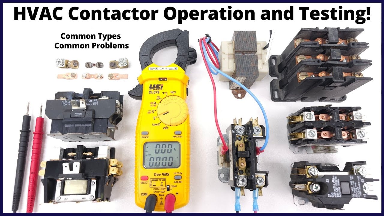
Watch the independent contactor overview on YouTube.
자주 묻는 질문
Can a standard multimeter capture pull-in current?
Often not reliably. The event may be shorter than its display update. Use a suitable DC current probe, shunt, recorder or inrush-capable instrument with adequate bandwidth and range.
Why measure coil voltage at the same time?
Voltage confirms what the coil actually received and separates coil behavior from supply, driver, connector and cable losses.
Is hold current enough to size the control output?
No. Check pickup current, hold duty, turn-off energy, switching frequency, voltage drop and the output group rating.
Can I calculate current from coil resistance?
Only when the exact coil behaves as the assumed circuit and temperature is known. Electronic or economized coils require their documentation and direct measurement.





