A contactor auxiliary contact rating must match the voltage, current, load type, switching frequency, fault protection, and required reliability of the control circuit. Do not choose it from the main contactor’s ampere rating. A small auxiliary contact that reliably reports a PLC input may be unsuitable for interrupting a DC contactor coil, while a contact rated for an inductive control duty may still have a minimum current below which signal reliability is not guaranteed. Select the exact NO or NC contact by its utilization category and manufacturer table, then validate the complete circuit and fault response.
Separate signal duty from switching duty
Auxiliary contacts commonly provide status, seal-in logic, electrical interlocking, alarms or controller feedback. Each function creates a different electrical duty. A PLC input may draw only milliamperes; a relay or contactor coil is an inductive load whose interruption produces a transient. A lamp can have a cold-filament surge. Do not use a single generic “10 A” number across those cases. Read the contact’s rated operational current at the actual control voltage and utilization category.
For IEC-style ratings, DC-13 is associated with switching DC electromagnets. Schneider Electric’s technical catalogue describes DC-13 for electromagnetic loads. This explains the category, but it is not a rating for a Sayoon auxiliary contact. Use the exact Sayoon drawing and data for the ordered option. For low-level signals, also request minimum permissible voltage/current or contact reliability data; a maximum rating does not guarantee dependable dry-circuit performance.
Collect the load information before selecting
Record whether the auxiliary contact makes, breaks or only carries the load; normal and fault voltage; steady and transient current; inductance or time constant; suppression; expected operations per hour and lifetime; ambient conditions; conductor size; and protective device. For controller feedback, include input leakage, diagnostic pulses and wetting-current requirements. For an interlock, document whether a normally closed contact must positively prevent the opposing coil from energizing and what happens if the contact welds, opens or is miswired.
| Application | Key rating evidence | Main risk | Verification |
|---|---|---|---|
| PLC status input | Minimum and maximum signal current/voltage, contact reliability | Oxide or leakage causes false state | Measure input thresholds over life and environment |
| Contactor coil switching | DC inductive category at actual voltage/current | Arc, erosion or welding on opening | Check category, suppression and endurance |
| Electrical interlock | NC contact duty and required fault behavior | Both coils commanded after contact failure | Fault test plus mechanical interlock where required |
| Indicator lamp | Inrush and steady lamp current | Cold-filament surge | Use lamp-specific manufacturer rating |
| Safety-related feedback | Defined contact architecture and safety data | Assuming ordinary auxiliary equals mirror contact | Validate complete safety function |
Check NO/NC state and mechanical relationship
“Normally” refers to the device’s defined de-energized condition. Confirm whether the selected block supplies NO, NC or changeover poles and map every terminal from the current drawing. Do not infer state from physical position or another model. For feedback, determine whether the auxiliary is mechanically linked in a way appropriate to the diagnostic claim. An ordinary auxiliary transition does not necessarily prove all main contacts opened or that hazardous DC voltage is absent.
Siemens documents auxiliary-circuit uses including signaling and interlocking and publishes model-specific low-level reliability boundaries. This reinforces two selection lessons: verify the intended function and use the exact device data. It does not transfer Siemens ratings to Sayoon products.
Account for suppression, protection, and endurance
When an auxiliary contact interrupts a coil, suppression changes arc stress and release time. A diode can reduce transient voltage but prolong DC coil current decay. A higher-voltage clamp may release faster while imposing more voltage on the switching device. Confirm compatibility with coil polarity, the contact rating and required timing. Do not add suppression when the coil already includes electronics without manufacturer approval.
Short-circuit protection does not turn an undersized auxiliary contact into an acceptable switch. Select a fuse or protective device within the manufacturer’s coordination guidance and conductor rating. Estimate electrical operations from real switching frequency and expected service life, not mechanical endurance alone. Environmental contamination, vibration and infrequent low-level operation can matter. Preserve replacement part numbers so maintenance does not substitute a block with a different contact material or category.
Commission the complete control function
- Verify the exact contactor, auxiliary block, terminal map and normal state.
- Identify load type, voltage, make/break current, suppression and switching frequency.
- Compare the manufacturer’s rating at the exact voltage and utilization category.
- Check minimum signal duty when feeding electronics.
- Confirm conductor, terminal and short-circuit protection requirements.
- Measure voltage and current during operation and capture the inductive transient if relevant.
- Exercise open-wire, welded-contact, stuck-coil and power-restoration scenarios defined by the design.
- Record state timing, contact resistance trend, drawings and replacement identity.
For an interlocking application, follow our DC contactor interlock guide. For controller status, the PLC 코일 제어 가이드 explains why command and feedback are separate. Use the selection guide to keep main-contact, coil and auxiliary requirements distinct.
Connect the choice to an actual product order
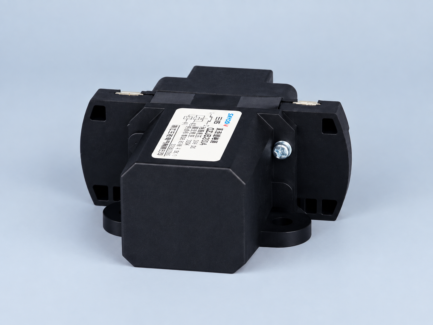
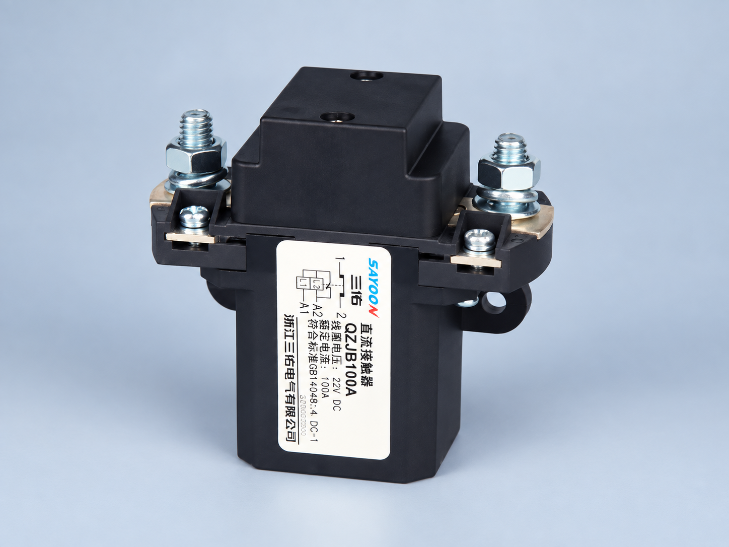
그 Sayoon QZJB200A product page is the featured product reference. A normally closed main-contact description does not automatically specify an auxiliary block. Send the required NO/NC count, signal or load details, control voltage, utilization duty, switching rate, life expectation, protection, environment and drawing requirements with the RFQ. Ask for explicit confirmation of terminal mapping and auxiliary ratings for the exact order code.
Avoid recurring selection mistakes
Do not use thermal carry current as make-and-break duty, apply an AC rating to a DC inductive circuit, assume a power contact will reliably switch microamps, count an ordinary auxiliary as a safety mirror contact, or treat a compatible mounting shape as electrical approval. Each shortcut removes a condition that manufacturers specify separately.
Contact bounce and controller filtering matter. A PLC may see several transitions during one operation, while another filter hides a slow change. Define timing from measured behavior. For seal-in logic, verify loss and restoration of power. For alarms, decide whether an open wire appears normal, alarm or fault. The electrical rating alone cannot answer those system questions.
Control replacements and maintenance
Record block model, position, terminal numbers, conductor range and permitted number of blocks. Mark installed NO and NC poles. During maintenance, verify de-energized continuity only after isolation, then perform an approved functional test. Low resistance at test current does not prove future inductive breaking capability.
If contacts fail, investigate load duty, suppression, frequency, contamination, loose terminals and fault current before installing a larger device. A relay interface separates low-level feedback from coil switching but adds its own coil, contacts, suppression and failure modes. Select the whole chain. For safety-related systems, use components and architecture supported by the applicable validation plan.
최종 설계 검토 및 증거 패키지
릴리스 전에 원래 설계자가 아닌 다른 사람에게 현장 상태의 배선을 승인된 도면과 정확한 제품 문서와 비교해 보십시오. 단자 식별, 도체 배선, 토크 증거, 보호, 코일 공급, 차단, 접점 상태 및 컨트롤러 설정을 확인하십시오. 모든 명시된 승인 한계가 추적 가능한 원천을 가지고 있으며, 설명적인 예가 비공식적인 제품 등급으로 전환되지 않았는지 확인하십시오. 사진은 설치를 확인할 수 있도록 도와주지만, 도면, 측정값 또는 제조업체의 확인을 대체하지 않습니다.
예정된 저온 및 고온 제어 공급 조건과 관련 있는 저온 및 고온 상태에서 반복적인 작동을 수행합니다. 동시 제어 부하, 현실적인 케이블, 인클로저 구성 및 예상되는 전환 순서를 포함하세요. 재설정 없이 예기치 못한 동작을 기록하고 버리세요. 필수 제품 값이 계속해서 사용 불가능한 경우, 해당 항목을 엔지니어링 검토 항목으로 표시하고 다른 접점과 유사한 방식으로 해당 기능을 승인하지 마십시오.
마지막 패키지를 구매 및 유지 관리와 제어 엔지니어링에 전달합니다. 이 문서에는 주문번호, 승인된 대체품, 도면 수정 사항, 테스트 설정, 원시 측정값, 통과 기준, 편차, 소프트웨어 버전, 보호 장치 식별 정보 및 교체 지침이 모두 포함되어야 합니다. 이는 시각적으로 유사한 코일이나 보조 블록이 나중에 다른 동작으로 설치되는 것을 방지합니다. 코일 옵션, 드라이버, 억제 기능, 케이블, 보조 접점, 제어 전압, 펌웨어 타이밍, 장착 또는 작동 환경이 현저하게 변경될 경우 재인증이 필요합니다.
마지막 검토 단계에서는 모든 제품 사진과 표시된 라벨이 주문한 제품의 실제 모델과 옵션과 일치하는지 확인해야 합니다.
Video: contactor interlocking context
This independent schematic lesson shows why auxiliary state is used in interlock logic. It is educational and does not provide Sayoon ratings.
Watch the interlocking circuit lesson on YouTube.
자주 묻는 질문
Can the main contactor current rating be used for the auxiliary contact?
No. The auxiliary circuit has its own voltage, current, load type, utilization category and endurance ratings.
Is a high maximum current rating enough for a PLC input?
No. Low-level inputs may require minimum switching current or contact-reliability data in addition to maximum ratings.
Can an ordinary auxiliary contact prove the main circuit is isolated?
Not by itself. Confirm the mechanical relationship and safety architecture, and use the required independent voltage or isolation verification.
Why does DC inductive duty matter?
Interrupting an electromagnet produces stored-energy stress and arcing. Use the exact DC utilization rating and approved suppression.





