A single break vs double break contactor comparison concerns the number of contact gaps opened in a conducting path. A single-break arrangement opens one contact interface in that path; a double-break arrangement opens two interfaces in series, often through a moving bridge. This description does not tell you the number of independently switched poles, the normal contact state, or the qualified DC interruption rating. Choose the device from its documented construction and operating duty, not the number of breaks alone.
This guide explains how equipment builders can compare construction, switching evidence, thermal behavior, insulation, and purchasing requirements without treating an exterior photograph as proof of an internal design.
Break count, pole count, and contact state are different
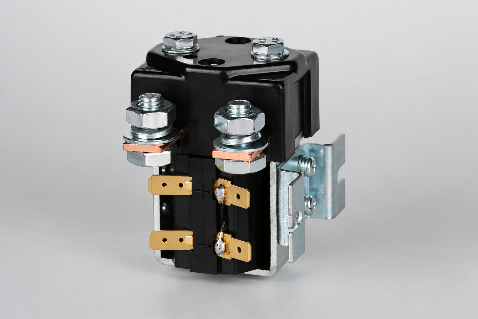
A pole identifies a controlled circuit path. A break identifies a contact separation within that path. One pole can contain more than one break. Two large external terminals do not show how many contact interfaces exist inside the housing, and four terminals do not automatically establish a particular internal switching arrangement.
Normally open and normally closed describe the contact state in the defined reference condition. They are separate from break count. An auxiliary contact arrangement is also separate from the construction of the main power contacts. Read the circuit diagram and the manufacturer’s construction information together.
Do not equate double break with double pole, changeover, or two independent devices. The mechanical linkage, conducting path, opening sequence, and insulation arrangement determine the actual design. If purchasing requires a particular construction, specify it explicitly and request the relevant evidence.
Understand the path before discussing interruption
In a common bridge arrangement, a moving conductor joins two fixed contact locations when closed. Opening separates both interfaces. The exact geometry, motion, contact force, travel, materials, and arc-control arrangement belong to the particular product. A general description should not be used to invent those details for a device whose construction is unknown.
For a single-break path, the opening event occurs at one main interface. That does not make it automatically inadequate for DC service. Different designs can use different arc-control methods, contact motion, and rated duties. Comparison must use the completed qualified device rather than isolated geometry.
Identify every connection in the power path, including internal contacts, terminals, and external joints. The complete path affects current carrying, temperature rise, voltage drop, and the electrical boundary after opening. Keep the construction information connected to the installation drawing.
Two gaps do not automatically double a voltage rating
During switching, the voltage distribution and arc behavior depend on the full circuit and device dynamics. Do not assume the two gaps always open at exactly the same instant or share voltage equally. The product’s qualified conditions must cover the intended use.
DC interruption requires an assessment of voltage, current, circuit characteristics, current direction where applicable, protection, and operating sequence. A construction description alone does not establish the ability to interrupt a particular load. Increasing break count is not a substitute for documented make and break evidence.
The university thesis Chalmers’ pre-study of arc-extinguishing techniques for a DC contactor provides research context for DC interruption. Its investigated arrangement is not a qualification for another device. Use research to understand questions to ask, and exact product evidence to approve hardware.
Compare requirements using a practical table
| Requirement | Evidence to request | Assumption to avoid |
|---|---|---|
| Internal arrangement | Approved diagram or construction description for the ordering code | Counting visible terminals identifies break count |
| DC interruption | Voltage, current, circuit characteristics, direction, repetition, and protection | Two breaks automatically give twice the voltage rating |
| Thermal duty | Installed current profile, contact path, joints, conductors, and enclosure | Break count alone predicts temperature rise |
| Open-state insulation | Applicable insulation and isolation evidence for the complete device | Two gaps automatically provide a maintenance isolation function |
| Life requirement | Electrical and mechanical life under the required duty | Unloaded operations equal loaded switching life |
| Replacement | Documented difference review including control and installation | Similar body shape establishes electrical equivalence |
The table is qualitative. It provides no universal gap distance, arc duration, switching voltage, current limit, or thermal coefficient. Those fields need product-specific and system-specific evidence.
Assess temperature rise across the whole path
For steady current, a simplified conduction-loss estimate is P = I²R. Use the resistance of the actual conducting path at operating temperature, including the relevant interfaces and joints. Contact force, material, surface condition, geometry, and cooling influence the result. The number of breaks alone does not determine total resistance.
As an arithmetic example, a hypothetical 100 A current through a total 2 milliohm path produces 20 W of conduction loss. That example is not a measured rating for the illustrated product. If two interfaces contribute to the total, use the supported installed values rather than assuming they have equal resistance.
Separate conduction loss from coil or holding-circuit consumption. Assess terminals, busbars, cable support, enclosure temperature, and operating cycle as part of the assembly. Comparing one room-temperature catalog value with another device’s installed hot measurement does not produce a fair conclusion.
Mechanical movement and contact wear need evidence
Review pickup and release timing with the exact driver, coil supply, suppression, and mounting. A mechanical design can have characteristic motion and contact behavior, but those properties must be measured or documented for the proposed option. A nominal coil voltage is not a timing specification.
Repeated loaded operations can change contact condition. Specify electrical life at the required switching duty separately from mechanical life. Neither a successful unloaded demonstration nor an operation-count headline proves suitability for a different load profile.
After the required qualification cycle, inspect the relevant contact and assembly condition through the approved procedure. Do not dismantle a sealed device merely to confirm a catalog claim if that action is not permitted. Request supplier construction and qualification evidence instead.
Open gaps are only part of the insulation assessment
The complete device includes contact gaps, housing insulation, terminal spacing, internal conductive parts, and interfaces to the installation. Determine the applicable insulation requirements and environmental conditions. Do not infer open-state capability from the external distance between terminals.
A maintenance isolation function requires the appropriate product evidence and complete system procedure. The applicable sources, stored energy, backfeed paths, and prevention of unintended reconnection must be assessed. Two internal gaps do not prove that the entire equipment assembly is safe to access.
IEC 60947-4-1 provides a standards reference for contactors and motor-starters within its scope. Confirm the applicable edition, classification, and qualification evidence for the exact product. Referencing the standard does not establish certification.
Verification in the actual circuit
Start with the operating-state matrix: startup, normal carry, planned stop, control-power loss, and defined abnormal events. State which conditions the contactor must switch itself and which depend on other protective or control functions.
Validate permitted supply and temperature boundaries with production-intent conductors, mounting, driver, suppression, protection, and software. Record voltage, current, coil behavior, feedback, temperature, and the timing of the assigned sequence. Establish pass criteria before testing.
Potentially hazardous interruption and fault tests require an approved qualified program. For service access, the applicable U.S. hazardous-energy control requirements provide workplace context where relevant. This article is not a live-work or test-circuit construction instruction.
Comparing proposals on the same basis
Create a side-by-side evidence record for the candidate devices. Use the same load waveform, supply envelope, temperature boundary, conductor arrangement, switching sequence, and required operation count. Mark any difference in the original test conditions before comparing the results. A favorable value without a matching condition can hide a requirement gap.
Keep measured data separate from estimates. A voltage-drop measurement describes the tested assembly and operating point; a simplified resistance calculation is a prediction with assumptions. Record instrument accuracy, temperature, current stability, and the points used for measurement so the result can be interpreted correctly.
If the supplier cannot establish internal construction, treat break count as unverified. You may still evaluate documented operating capabilities, but you should not publish or purchase against an unsupported construction claim. Resolve the missing evidence before assigning a requirement that depends on that feature.
Purchasing and substitution checklist
The RFQ should specify the required conducting paths, normal contact arrangement, construction evidence, voltage and current envelopes, make and break events, control supply, suppression, feedback, installation, environment, protection, and life. Ask which requirements are covered by existing evidence and which need additional review.
Preserve the complete ordering code and drawing revision. A substitution that changes the internal arrangement also needs assessment of switching, thermal, insulation, control, and mounting behavior. Do not approve equivalence from appearance or break count alone.
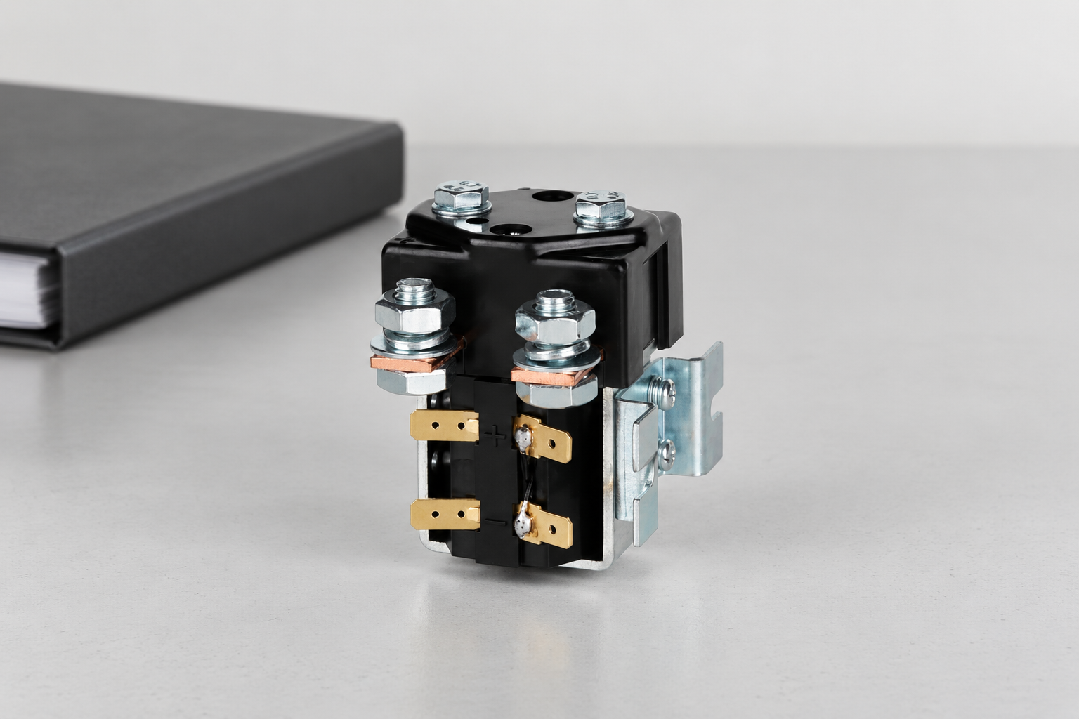
그 CZWb100A product page provides an exterior construction reference for document requests; no internal break count is asserted here. Read the specification guide, coil control guide, 그리고 electrical life guide for complementary requirements.
Electrician U’s video explains basic contactor operation. It provides background rather than proof of the illustrated product’s internal construction.

자주 묻는 질문
Does double break mean double pole?
No. A pole identifies a controlled path; a break identifies a contact separation within a path.
Does double break automatically double the voltage rating?
No. Use the exact device’s documented switching and insulation conditions.
Can an exterior product image establish break count?
No. Request the approved internal construction description or diagram.
What makes a replacement equivalent?
Documented matching functions and applicable switching, thermal, insulation, control, installation, and qualification evidence.





