DC contactor and circuit breaker coordination means defining how normal switching, fault detection, protective interruption and recovery work together for the actual DC circuit. Review the exact breaker’s DC application conditions, the contactor’s documented duties, the source fault assessment and any required component-combination evidence. Two suitable-looking devices do not automatically form a verified protection system. Specify which device opens for each event and what the controller may command before and after protection operates. Validate the arrangement through applicable evidence and authorized testing, and keep the final approval tied to the exact components and circuit configuration.
Begin with an event map
List routine start-up, shutdown, overload, short circuit, loss of control supply and recovery after a protective operation. Assign the intended response for each event. A contactor can manage routine switching while a protective device performs another function, but the division of responsibility must be explicit. Do not assume that any device that opens a circuit can perform every interruption duty.
Record the source, main current path, control supply and detection signals on the schematic. Identify which signals remain available during the event. An elegant controller sequence is ineffective if the supply powering the diagnostic disappears before it can act. Review the hardware response and controller logic together, with the responsible electrical and controls engineers.
Confirm the breaker’s actual DC application conditions
Read the exact breaker markings, instructions and rating documentation. Check the applicable DC voltage, interruption capability and any required pole arrangement or polarity. An AC marking or a familiar housing is not sufficient evidence. The complete installed arrangement must follow the documented conditions; do not invent a series-pole connection from an unrelated example.
UL’s breaker marking and application guide explains that application depends on the device’s markings and conditions. Use it as a reference for reading the evidence, not as approval for a particular battery system. Obtain the documentation for the exact proposed breaker and retain the applicable instructions with the design.
Define what the contactor must withstand and switch
Specify normal carrying, making and breaking duties independently from the fault-clearing function assigned to the breaker. Include voltage, load characteristics, switching repetition and installation conditions. A contactor ampere number alone does not explain what it can interrupt. Review the exact variant and any limitations relevant to the required sequence.
Identify whether the contactor is expected to remain closed during a protective interruption or open in response to another command. That decision needs applicable evidence and timing assumptions. Do not command an unsupported fault interruption merely because a breaker is upstream. The presence of a protective device does not erase the contactor’s own duty limits or establish a withstand value.
Use a source-specific fault assessment
Obtain the available fault-current assessment for the relevant point in the circuit. Include source configurations that change the fault path or current contribution. Battery, converter and mixed-source systems should not be treated as identical just because their nominal voltages match. Record the assessment basis, relevant impedance and the operating conditions included by the designer.
Check the breaker interruption evidence and the contactor protection evidence against that assessment. A system current limit may influence the design, but it must be documented rather than assumed from a product description. Missing source behavior is an unresolved input. Do not turn the ordinary load current into a short-circuit value or infer a fault rating from successful normal operation.
Review component-combination evidence carefully
UL publishes information about specified motor-controller combinations. This demonstrates why a combination rating belongs to a defined set of components and conditions. Those motor-controller listings do not automatically establish the rating of a DC energy-storage circuit or a different protective arrangement.
For your application, identify the exact breaker, contactor, voltage, wiring and conditions covered by the applicable evidence. Record any required accessories or installation restrictions. If a component is substituted, ask which approval or test basis must be reviewed. A general certificate and two individual ratings should not be presented as equivalent to evidence for the proposed combination.
Examine the timing and command assumptions
Build a sequence that distinguishes detection time, controller processing, device response and mechanical or electrical interruption. Use applicable data for the exact devices and conditions. A nominal response time taken from one test can be unsuitable for a different supply or load. Keep uncertainty visible instead of producing a precise timing diagram from unsupported values.
Check what happens if the contactor does not reach the commanded state or an auxiliary signal is inconsistent. Define the fault handling and restart restriction. A controller should not repeatedly attempt a routine close after a protective event without the approved recovery conditions. The event sequence is a design decision, not a universal script that can be copied between unrelated machines.
검토를 위한 결정 체크리스트
이 질적 체크리스트는 프로젝트 검토를 체계화합니다. 이 체크리스트는 문서화되지 않은 등급을 부여하거나 정확한 공급업체 지침을 대체하지 않습니다. 해결되지 않은 항목에 대한 소유자를 명시하고 제안된 주문 코드, 회로 조건 및 제어된 증거에 따라 각 결정을 기록합니다.
| 확인 | 필수 증거 | 결정 또는 기록 |
|---|---|---|
| Events | Start, stop, overload, short circuit and recovery map | Assign the intended action and responsible device for each event. |
| Breaker | Exact DC markings and application instructions | Verify voltage, fault capability and required pole or polarity conditions. |
| Contactor | Carrying, switching and protection evidence | State the required duty without deriving it from breaker ratings. |
| Source | Available fault-current assessment | Include relevant operating configurations and source behavior. |
| Combination | Applicable exact-component evidence | Match variants and installation conditions; review substitutions. |
| Control | Detection, command, response and diagnostic sequence | Identify missing signals, uncertainty and restart restrictions. |
| Verification | Approved checks, testing and recovery instructions | Retain the configuration and scope of the release decision. |
Distinguish protection coordination from device comparison
Comparing the roles of a contactor and a breaker explains why both may appear in a circuit. Coordination goes further: it assigns actions and reviews their interaction under defined events. Keep that distinction in the design record. A table listing component advantages cannot replace a source assessment, applicable ratings and the control sequence.
Also distinguish coordination between contactor and breaker from selective coordination among several protective devices. If upstream and downstream breakers are involved, the protection designer must review that separate requirement using applicable data and methods. Do not claim selectivity because one protective device has a smaller current number or is physically closer to the load.
Review installation and connection details
Check conductors, terminals, barriers, orientation, enclosure conditions and service access against the device instructions. Record any required pole arrangement directly on the controlled drawing. Ensure the production instruction reproduces the approved design. An undocumented wire change can invalidate the intended protection behavior even if the component ordering codes remain unchanged.
Include the control-circuit routing and suppression arrangement. Coil circuitry and diagnostic wiring need their own review and should not be confused with the main protection path. Verify that service personnel can identify both devices and their isolation requirements. A contactor’s open command is not a substitute for the approved safe-isolation procedure.
Define inspection after protection operates
Specify which records and components must be examined after a protective event. Preserve controller logs, breaker indications and observed contactor state when available. Ask the responsible engineer whether the contactor, terminals or other equipment need inspection or replacement before return to service. Do not assume that a breaker reset proves the whole circuit is ready to operate.
Recovery instructions should identify who may authorize a restart and which fault cause must be resolved. Avoid automatic reclosing or repeated contactor cycling unless the approved system design explicitly supports that behavior. Keep the event history linked to the installed variants so a later investigation can distinguish a design issue from an unauthorized substitution or installation change.
Validate the arrangement without an improvised fault test
Confirm component identity, drawing conformity, control sequence and diagnostic behavior under an approved plan. Separate routine functional checks from fault-related verification. High-energy testing requires an appropriate facility, procedures and safety controls. A manual battery short or uncontrolled switching demonstration is not evidence of coordination and can damage the assembly.
Retain the test configuration, source conditions, procedures, results and final review decision. Document the limits on the conclusion, including any untested conditions. When the source, breaker, contactor or wiring changes, identify which evidence is affected. The final approval should describe a specific arrangement, not a broad statement that every device in two product families coordinates correctly.
사윤을 위한 집중적인 조사를 준비하세요.
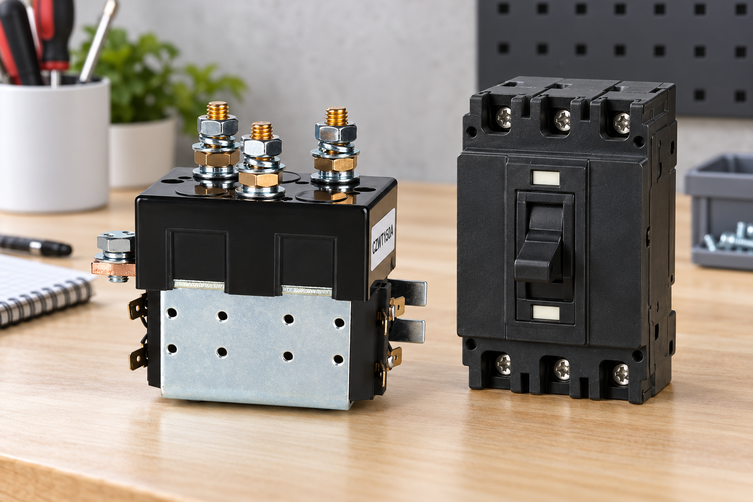
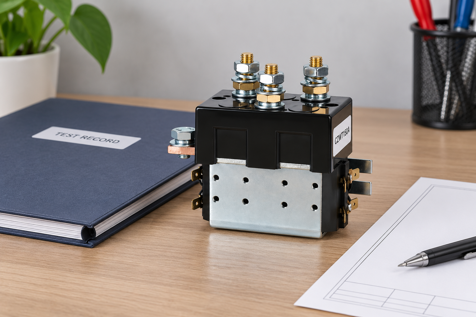
그 CZWT150A DPDT 반전형 DC 접촉기 이 그림은 해당 구조물의 설계 참조입니다. 이 사진은 전기 성능, 적용 승인 또는 적합한 대체품에 대한 정보를 제공하지 않습니다. 변형을 선택하기 전에 현재 도면, 정확한 코일 옵션, 접촉 배열 및 해당 증거를 Sayoon에게 문의하십시오. 필수 요건과 조건을 명시하여 응답이 실제 회로에 적용되도록 하십시오.
사용하세요 DC 접촉기 선택 허브 응용 프로그램 사양을 구성하기 위한 작업. Device-role comparison provides background; 시험 보고서 검토 helps check the evidence scope. Include the unresolved questions and your acceptance method in the inquiry. A complete evidence request is more useful than a request for a visually similar unit or a generic claim that a model is equivalent.
교육용 동영상: 제어부와 주 회로 구분하기
The Electrician U explanation shows how a control coil operates main contacts. Use it to understand why a controller command and a protective interruption are different parts of the event sequence. It is general education, not a coordination study or fault-test instruction. The exact devices and circuit still require their applicable documentation and approved validation.

자주 묻는 질문
Do individual component ratings prove coordination?
No. Review the interaction, source conditions, sequence and any required combination evidence for the actual arrangement.
Can an AC breaker be assumed suitable for DC?
No. Obtain applicable DC markings and instructions for the exact device and installation.
Is coordination the same as comparing device roles?
No. Coordination defines event actions and checks how the devices work together under specified conditions.
Does resetting a breaker prove the contactor is undamaged?
No. Follow the approved post-event inspection and recovery requirements for the complete equipment.





