A 60A DC contactor specification should describe how the load reaches sixty amperes and what happens when the circuit is switched. For an auxiliary supply, heater branch or intermittent machine load, the same average current can conceal different peak, thermal and interruption requirements. Define the main voltage, current profile, switching conditions, coil supply and protective coordination together. This guide emphasizes duty-cycle interpretation and control stability. The construction example is not a promise that every sixty-amp circuit is supported by the pictured variant.
Identify the operating phases rather than quoting an average
Separate standby, startup, normal operation, overload and shutdown in the current record. Note how long each phase lasts and how often the cycle repeats. An average from a controller screen can hide brief demands that matter to the contacts and connections.
If 60A is a measured operating value, record the measurement point and conditions. The main branch can differ from an individual load, particularly when other auxiliaries share the contactor. Include simultaneous demand rather than assuming every component runs separately.
The load profile should also identify the circuit’s temperature history. Repeated operation after a short pause can begin with warm terminals and a warm coil. A test from a cold specimen may therefore answer a different question from the actual production cycle. Give the supplier those distinctions before selecting a nominal-current class.
Use RMS current only for the question it can answer
For an illustrative repeated profile of 80A for 2 seconds and 20A for 8 seconds, the ten-second RMS current is sqrt((80²×2 +20²×8)/10) =40A. These arbitrary values explain a calculation method; they are not an approved duty for any product.
RMS current can help characterize resistive heating, but it does not erase the 80A peak or establish DC making and breaking capability. The actual contactor’s thermal dynamics, timing and installation still matter. Nor does a 40A RMS result automatically make a 40A catalog part suitable.
Use the complete waveform or time profile when asking for supplier review. Distinguish the thermal question from mechanical operation and switching events. If the load is electronically controlled, include behavior during startup, a control fault and loss of supply, rather than assuming the controller always limits current successfully.
Check voltage drop and heating at the connections
A steady sixty-amp circuit can make connection quality important even when the contactor has ample nominal carrying capacity. In an illustrative 1 milliohm resistance, V = IR gives 0.06V at 60A, while P = I²R gives 3.6W. This is a hypothetical connection example, not product data or an acceptance limit.
A measured voltage drop can help locate a resistive region when the test is performed under controlled, appropriate conditions. It should be interpreted with current, temperature, measurement accuracy and the manufacturer’s guidance. Do not use one arbitrary millivolt figure as a universal reject threshold.
Check the conductors, lugs, terminal fastening and physical support together. A loose or stressed connection may undermine a suitable device. Correct the installation problem rather than interpreting every hot terminal as evidence that the contactor’s nominal current class was too small.
Describe the opening event and the load circuit
Determine whether the contactor opens at full load, after another controller reduces current or under a defined abnormal condition. The sixty-amp operating figure alone does not settle interruption. Load inductance, source voltage, direction and repetition can affect the applicable DC duty.
For a heater branch, verify the element’s cold and operating behavior. For an auxiliary motor, identify starting and stalled conditions. For an electronic supply, describe input capacitors and any charging sequence. These loads should not be grouped as interchangeable simply because their nameplates use similar current numbers.
Ask for evidence that matches the assigned event. A contactor intended mainly to carry current may depend on another device for fault protection. Avoid creating a new emergency-opening requirement during replacement without reviewing whether the candidate construction supports it.
Prevent coil supply dips from creating unintended cycles
The main load can disturb the same supply or wiring system that operates the coil. Review the coil voltage at pickup and during the load transition, including the control-output device and conductor path. A supply with a correct unloaded voltage may still dip during an operating event.
Obtain the pickup, hold and release requirements for the actual coil option. Do not generalize across DC, AC, economized and latching variants. Identify polarity and suppression before connecting the driver. A poorly understood suppression arrangement can change release behavior or increase stress on the output stage.
If the equipment experiences chatter or unintended dropout, treat that as a control-system problem requiring investigation. Increasing the contactor’s catalog current cannot by itself stabilize the coil supply. Validation should reproduce the approved operating conditions and verify both coil behavior and main-path response.
Review installation limits for an intermittent machine
Intermittent duty can look forgiving, but the installation still determines heat transfer and mechanical reliability. Specify ambient conditions, enclosure arrangement, neighboring heat sources and conductor construction. Record whether the machine repeats a cycle rapidly or starts again after a cooling interval.
Follow the selected model’s mounting and terminal instructions. For a contactor with exposed mechanical features, provide the required protective enclosure and maintain clearances. The external appearance of a sample does not demonstrate every environmental suitability or approval needed by the machine.
Account for vibration, conductor support and maintenance access. A convenient replacement bracket may change mechanical loading or temperature conditions. Include those changes in the design review rather than treating them as unrelated assembly details. The final installed configuration is the configuration that needs to meet the duty.
Set an acceptance plan that separates evidence types
Incoming checks should confirm identity, coil option, contact arrangement and drawing revision. Functional checks should observe pickup, hold, release and feedback under a suitable controlled procedure. Thermal checks should represent the agreed current profile and installation. These are different evidence types and should have separate records.
An unloaded click test is not a 60A application qualification. Likewise, a sample that remains cool during one benign carrying test has not demonstrated every closing or opening event. Write the question each test answers and avoid extending its conclusion to untested conditions.
Retain the conditions and results with the sample identification. If the supplier changes a coil, contact material, suppression module or construction, review the impact on the original acceptance basis. Do not assume that a shared family name makes every revision equivalent.
Prepare a supplier-ready sixty-amp duty packet
Provide the full operating current profile, voltage range, load description, making and breaking events, coil conditions, protection and environment. If the requirement is intermittent, state exact durations and repetition. If sixty amperes is continuous, say so explicitly and describe the installed thermal configuration.
Request the supported ordering code and the conditions attached to its ratings. Ask the supplier to flag unsupported events or missing information before quoting an apparently equivalent part. This helps distinguish a supported proposal from a headline number that answers only part of the requirement.
For an existing machine, include its approved sequence, original part code and reason for replacement. A change in default contact state, feedback or release behavior must be evaluated even when the new model’s nominal current is higher. Preserve a traceable acceptance record for future repeat orders.
선정 증거 체크리스트
| 리뷰 필드 | 제출해야 하는 정보 | 수용 범위 |
|---|---|---|
| 프로필 | Current with duration and repetition | Do not use the average alone |
| Thermal evidence | Installed enclosure and connections | RMS does not prove switching capability |
| 개최식 | Current, voltage and load conditions | cURL Too many subrequests by single Worker invocation. To configure this limit, refer to https://developers.cloudflare.com/workers/wrangler/configuration/#limits |
| cURL Too many subrequests by single Worker invocation. To configure this limit, refer to https://developers.cloudflare.com/workers/wrangler/configuration/#limits | cURL Too many subrequests by single Worker invocation. To configure this limit, refer to https://developers.cloudflare.com/workers/wrangler/configuration/#limits | cURL Too many subrequests by single Worker invocation. To configure this limit, refer to https://developers.cloudflare.com/workers/wrangler/configuration/#limits |
| 환경 | cURL Too many subrequests by single Worker invocation. To configure this limit, refer to https://developers.cloudflare.com/workers/wrangler/configuration/#limits | cURL Too many subrequests by single Worker invocation. To configure this limit, refer to https://developers.cloudflare.com/workers/wrangler/configuration/#limits |
| 변경 제어 | cURL Too many subrequests by single Worker invocation. To configure this limit, refer to https://developers.cloudflare.com/workers/wrangler/configuration/#limits | cURL Too many subrequests by single Worker invocation. To configure this limit, refer to https://developers.cloudflare.com/workers/wrangler/configuration/#limits |
이 질적 체크리스트는 증거를 체계적으로 정리합니다. 여기에는 제품 평점이나 보편적 수용 범위가 명시되어 있지 않습니다. 다른 곳의 수치적 예들은 명시적으로 가설적인 것입니다.
제품 정보 및 관련 검토 도구
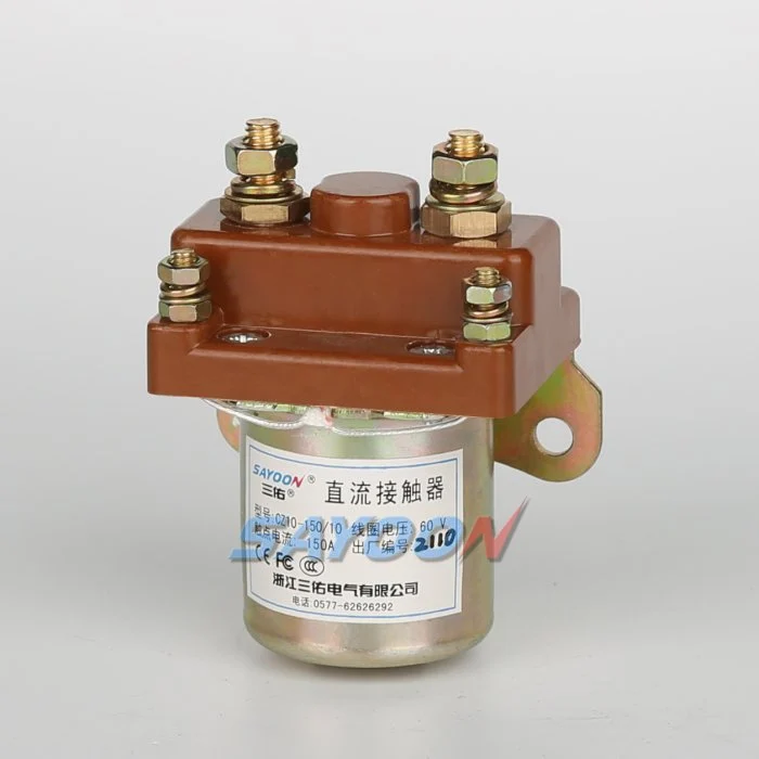
그 cURL Too many subrequests by single Worker invocation. To configure this limit, refer to https://developers.cloudflare.com/workers/wrangler/configuration/#limits 표시된 외장 구성에 대한 참조입니다. 사진에 나온 모델은 요구 사항과 다른 전류 등급이나 접촉 배열일 수 있습니다. 이 제품은 모든 구성이 지원된다는 자동적인 권장이나 선언이 아닙니다. 선택하기 전에 정확한 주문 코드, 도면 및 해당 등급을 확인하십시오.
사용하세요 OEM 사양 증거 목록 증명된 한계와 해결되지 않은 가정들을 분리하기 위해. 메인 회로 검토를 보완하기 위해 코일 전압 허용 오차 그리고 기계적 수명 대 전기적 수명. 이러한 주제들은 이 문서의 선택 영역을 대체하는 대신, 서로 다른 제어 및 라이프사이클 관련 질문들을 다룹니다.
소스 및 안전한 검증
범위 참조: IEC60947-4-1 접촉기 및 모터 스타터 표준 개요; 미국 전기 작업 실무 요구 사항. 관련 장비 요구 사항 및 승인된 제조업체의 문서를 적용하십시오. 이러한 링크는 제안된 용도에 대한 해당 제품의 인증을 제공하지 않습니다. 명령된 접촉 개방은 서비스 전에 적절한 차단 및 검증을 대체하지 않습니다.
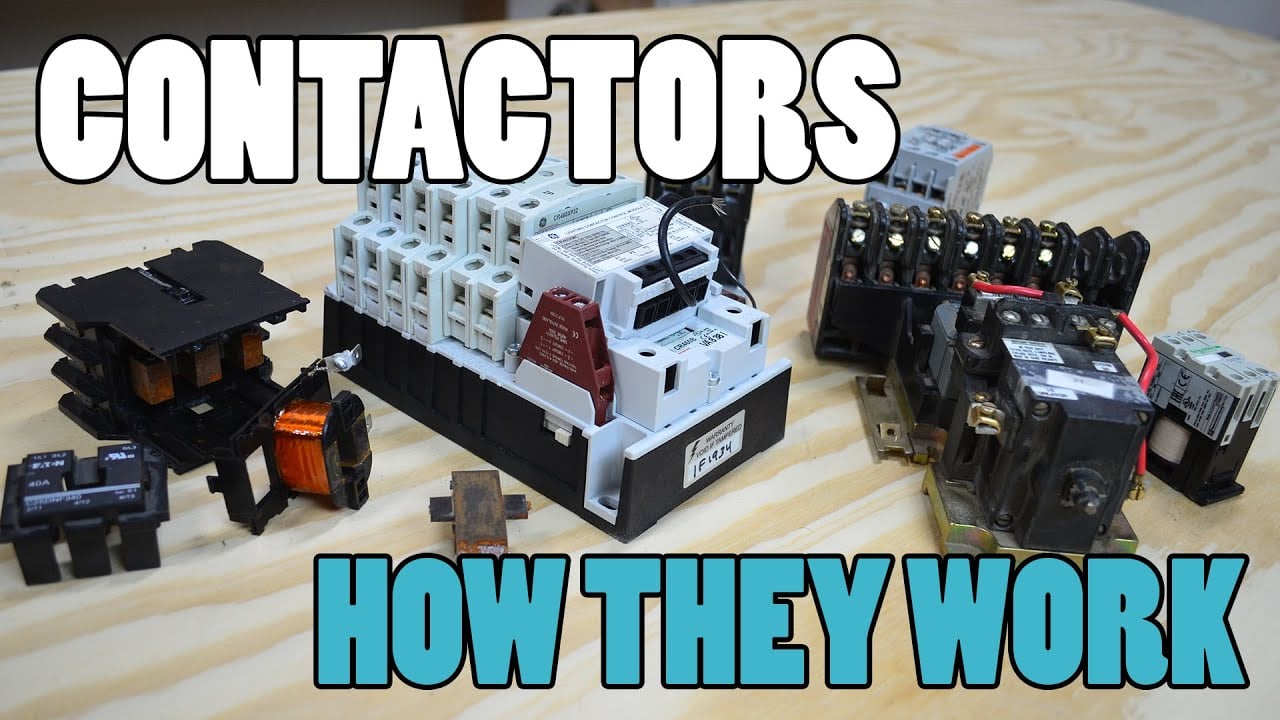
교육 접촉기 메커니즘 영상
전기 기술자인 U는 전자기 작동 원리를 설명합니다. 이는 특정 전압, 전류, 보호 기능 또는 해당 제품의 인증 여부와는 무관하게 코일 및 접촉 작동에 대한 이해를 뒷받침합니다. 비디오를 시청하든 시청하지 않든 해당 기사의 선택 근거는 여전히 필요합니다.
자주 묻는 질문
낮은 RMS 전류가 피크를 무의미하게 만드나요?
No. RMS는 가열을 알릴 수 있으며, 피크 및 스위칭 이벤트는 별도의 요구 사항으로 유지됩니다.
3.6W는 허용된 제품 손실입니까?
아닙니다. 이는 임의의 저항값을 사용한 예시적인 I²R 계산일 뿐이며, 정격이나 한계값을 의미하지 않습니다.
더 큰 용량의 접촉기를 사용하면 코일 채터링 문제를 해결할 수 있습니까?
Not by its main-current rating alone. Investigate coil supply, driver, suppression and the operating sequence.
What distinguishes intermittent from continuous 60A duty?
The duration, repetition and thermal starting conditions must be documented; the label 60A does not express them.