Snel antwoord: A BESS emergency stop contactor sequence must follow the system hazard analysis. It should command the PCS to remove current when time permits, open the required DC isolation devices within their qualified duty, block further charge or discharge, initiate controlled bus discharge, verify the resulting state with independent feedback, and prevent automatic restart. An emergency-stop button alone does not define a safe electrical state.
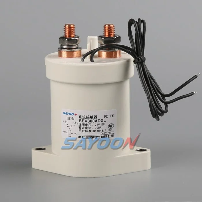
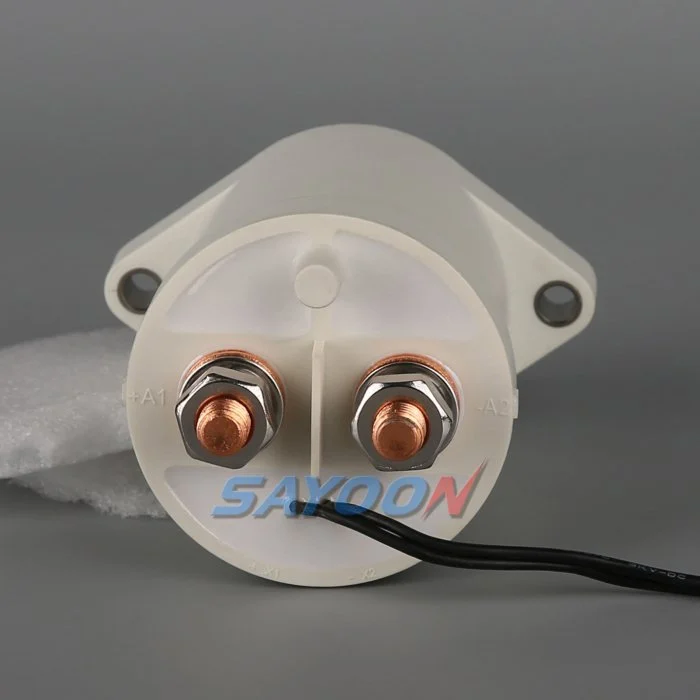
This guide turns the topic into a reviewable BESS design, controls, commissioning, sourcing, and service workflow. It uses a real Sayoon product image while keeping every electrical and safety decision tied to the final system, applicable standards, and current product documentation.
Engineering besluitkaart
| State or element | Expected condition | Engineeringfocus |
|---|---|---|
| Operator emergency stop | Latched stop request | Remove hazardous operation and require deliberate reset |
| Detected electrical fault | Fast coordinated protective action | Respect contactor, fuse, PCS, and battery limits |
| Fire or thermal event | Site-specific isolation and emergency response | Avoid assumptions about opening under extreme current |
| Reset request | No restart until all safe-state conditions pass | Separate reset from automatic re-energization |
Productreferentie en toepassingsgrenzen
De SEV300ADXL sealed high-voltage DC contactor is a real product-family example. Review the Hoogspannings-DC-contactoren en Selectiehandleiding voor DC-relais for adjacent decisions. A product image, family name, or nominal current is not approval for a particular BESS. Confirm the exact order code, drawing, coil, main-circuit duty, insulation, environment, life, mounting, control, feedback, and protection.
Start with the hazard and required stop
Emergency stop is a risk-reduction function, not a universal wiring pattern. Identify the hazardous motions, electrical energy, thermal conditions, stored capacitor energy, and sources that can back-feed the bus. Define which equipment must stop, which circuits must isolate, what may remain energized, and how the state will be verified.
The sequence for an operator-access emergency can differ from a short circuit, insulation fault, fire signal, cooling loss, or battery thermal event. Each initiating event should map to a reviewed response rather than one undifferentiated coil-drop command.
Do not confuse control stop with isolation
The PCS may stop switching power while the DC bus remains energized. Opening one contactor may isolate a battery string while the common bus stays live from other racks. Removing coil power may not open welded contacts. The design must state the boundary created by the positive and negative mains, string devices, converter disconnects, and service disconnects.
Use pack-side and bus-side voltage sensing, string current, coil current, and auxiliary feedback to verify what actually happened. Labels and procedures must describe remaining energy after an emergency action.
Reduce current before opening when permitted
A controlled command to the PCS can reduce DC current before the contactors open, limiting arcing and preserving electrical life. The available delay depends on the hazard. A rapidly developing fault may require the fuse or another protection device to act without waiting for software.
Define a maximum allowed delay and the fallback if the PCS does not acknowledge or current does not fall. Never assume that sending a zero-current command proves the measured current reached an acceptable level.
Coordinate contactors and fault protection
Contactors provide controlled switching; fuses clear specified fault currents; a pyrotechnic disconnect or breaker may provide another isolation function. State which device acts first for each fault and what current the contactor must withstand or interrupt. Include current from all parallel racks and the converter.
Opening outside a verified DC break rating can worsen arcing or fail to isolate. Protection coordination should use the exact voltage, current direction, inductance, clearing time, and installation.
Design a fail-aware control path
The emergency-stop chain should be monitored according to the safety architecture adopted by the project. A broken control wire, welded output, shorted driver, loss of control power, communications failure, or failed sensor must lead to a defined state. Redundant channels require independent fault detection, not merely duplicate software bits.
Suppression changes coil release time and driver stress. Confirm the actual coil option, driver topology, flyback path, and release distribution at control-supply and temperature boundaries.
Verify opening and bus discharge
After the command, confirm coil current ends, auxiliary state changes, string current stops, and the expected voltage separation appears. Then verify the discharge circuit reduces the relevant bus section according to the project requirement. A timer is not proof of safe voltage.
Parallel sources and converter capacitors can keep a section energized. The logic must detect failed discharge, welded contacts, back-feed, and sensor disagreement and prevent reset while the state is uncertain.
Prevent unintended restart
Resetting an emergency-stop device should not automatically energize the BESS. Require the initiating condition to clear, emergency devices to reset, isolation and discharge checks to pass, interlocks to be healthy, the PCS to be ready, and an authorized start command. Record who or what issued the restart.
After a severe event, the procedure may require inspection of contactors, fuses, busbars, terminals, sensors, cooling, enclosure, and batteries before release. Software should not bypass that decision.
Test the complete response
Perform staged tests with production-intent hardware and approved simulators. Verify operator stop, communications loss, low control supply, stuck coil driver, delayed release, welded feedback, failed voltage sensor, PCS nonresponse, discharge failure, and attempted restart. Capture all commands, currents, voltages, feedback, and timestamps.
Confirm that one fault in the stop chain is detected and that the resulting state matches the safety requirements. Retain raw data, limits, instrument details, software revision, and deviations.
Specify the emergency duty in the RFQ
Provide maximum system voltage, current at the moment of emergency opening, current direction, inductance, prospective fault current, fuse clearing, maximum opening time, coil supply, driver and suppression, feedback arrangement, temperature, environment, life, and required standards.
The SEV300ADXL shown here is a product reference. Final approval requires product-specific evidence for the exact emergency duty and installation. Include the required action after loss of auxiliary power, the maximum accepted bus voltage after stopping, the manual reset location, remote-stop interfaces, inspection rules after a severe event, and the evidence required before re-energization. Ask the supplier which duties are covered by published data and which require project-specific testing.
Veiligheids- en bewijskwaliteitscontroles
Treat batteries, the common bus, converter capacitors, parallel racks, auxiliary supplies, and test equipment as hazardous energy sources until an authorized person has applied the site isolation procedure and verified the required state with rated instruments. Do not bridge feedback, force a coil, defeat interlocks, or open a device outside its qualified switching duty. A simplified schematic can hide stored energy and reverse energization.
Build acceptance limits from exact product data, approved system requirements, and representative testing. Record the complete part number, drawing revision, conductor arrangement, instrument locations, calibration, temperature, software version, raw waveforms, pass/fail limits, deviations, and reviewers. Separate measured facts from interpretations. Record missing evidence as an open action instead of inserting a typical value.
Change control and maintenance
Review the original evidence when the battery configuration, PCS firmware, busbar, fuse, cable, cooling, voltage sensor, current sensor, contactor coil option, driver suppression, discharge component, or operating schedule changes. The assembly may look unchanged while make current, opening current, timing, thermal stress, or insulation has moved outside the validated envelope.
During maintenance, inspect terminals, barriers, conductors, heat evidence, contamination, mounting, control wiring, and stored faults. Compare voltage drop, temperature, and timing only under comparable conditions. After replacing a contactor, fuse, sensor, controller, or resistor, repeat the approved start, load, stop, isolation, discharge, feedback, and restart-inhibit sequence before returning the rack to service.
Gerelateerde Sayoon-gidsen
Gebruik de BESS main contactor placement guide, parallel battery-string contactor guide, feedback plausibility guide, gids voor de afmetingen van precharge-weerstanden, en Gids voor openingstijden en sluitingstijden as complementary checks. They address separate decisions within the same controlled boundary.
Educatieve video
Wat is een contactor en hoe werkt het? by Electrician U provides visual background directly related to this topic. It does not replace the written requirements, product data, calculations, or site safety procedure.
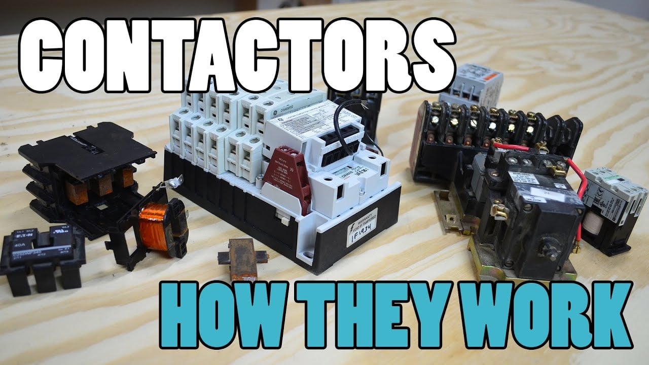
Bekijk de educatieve video op YouTube.
Veelgestelde vragen
What is the key verification for bess emergency stop contactor?
Use independent electrical evidence at the defined isolation boundary; do not rely on a command bit, timer, or auxiliary contact alone.
Can an auxiliary contact prove the high-voltage path is safe?
No. Correlate it with voltage, current, coil behavior, timing, and every possible parallel or back-feed path.
Can one universal timing limit be used?
No. Establish timing from the exact contactor, driver, suppression, sensors, capacitance, temperature, supply, and approved system tests.
What belongs in the design record?
Keep the circuit boundary, exact parts, drawings, operating waveforms, calculations, test conditions, raw data, acceptance criteria, deviations, and approvals.
Betrouwbare referenties
- OSHA 1910.147 — controle van gevaarlijke energie
- OSHA 1910.333 — praktijken bij elektrotechnische werkzaamheden
- IEC 60947-4-1 — contactoren en motorstarter
- Ministerie van Energie van de VS — energieopslag
Gebruik de door het project aangenomen edities en vereisten. Normen en productgegevens kunnen veranderen, dus moet het verantwoordelijke technische team het definitieve ontwerp bevestigen.





