An 80A DC contactor should be selected from the complete motor or load-control circuit, including its pole arrangement and switching sequence. Eighty amperes may describe normal running current, but it does not establish startup, stalled-current, reverse-current or fault duty. Separate main-contact capability from coil voltage and feedback. For motor-control equipment, a two-NO contactor is not automatically a reversing assembly, and a single nominal-current figure does not validate an interlock. This guide focuses on architecture and transition evidence before a purchasing decision.
Locate the contactor relative to the motor controller
A contactor placed at a drive’s DC input serves a different boundary from a device switching the motor conductors directly. Draw the source, drive, motor and any charging or precharge path. Identify exactly where the proposed contactor sits and what function it performs.
At a controller input, closure can involve DC-link capacitors, while the controller normally handles motor current modulation. At a direct motor path, the contacts may encounter different inductive and starting conditions. Do not move a contactor between these positions merely because both circuits are called 80A.
Describe normal operation, shutdown, stalled load and loss of control. The drawing should show which device controls the current during each transition. That information is necessary before the supplier can assess making, carrying and breaking duty for the assigned position.
Define poles and contact states without inferring reversal
Pole count, normal contact state and circuit function are separate characteristics. Two normally open poles can switch two defined paths, but they do not automatically form a reversing arrangement. A reversing circuit requires an approved architecture and appropriate control of incompatible states.
Identify each main pole and any auxiliary contact on the drawing. A small feedback terminal is not a substitute for a high-current pole. Similarly, an NC auxiliary contact does not establish that the main motor circuit is normally closed. Review the respective ratings and functions separately.
For a replacement, compare the exact contact diagram with the equipment schematic. If the pole form changes, treat that as a design change. Matching 80A, the coil voltage and mounting size is insufficient when the altered contact arrangement changes how the motor or controller is connected.
Review interlocks and transitions as system functions
Where equipment has incompatible switching states, determine how the control system prevents simultaneous commands and confirms the necessary transition. Do not rely on a product-family label to prove an electrical or mechanical interlock that has not been documented.
Define the sequence for commanded stop, a direction change if applicable, failed feedback and power recovery. State what must be confirmed before another path can be enabled. Release behavior, stored control energy and suppression may affect timing, so verify the exact coil and driver configuration.
A contactor image does not show the complete control logic or prove a safe reversing sequence. Retain the approved circuit and validation evidence. If the proposed part changes feedback, contact state or mechanism behavior, review the impact before installation rather than discovering the difference during machine operation.
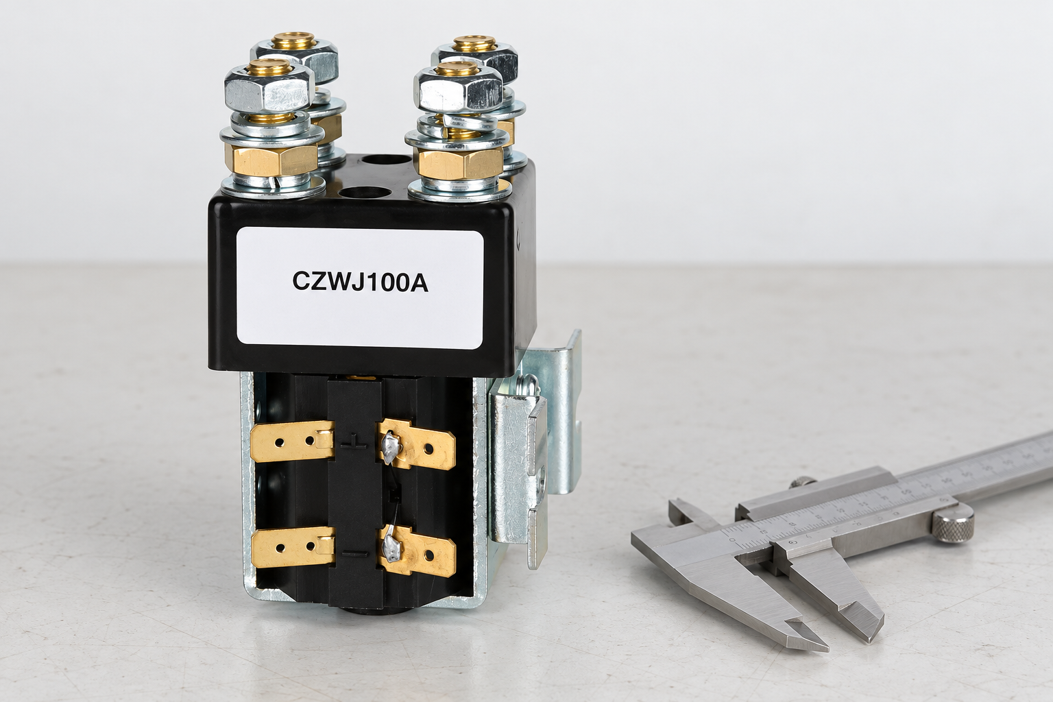
Characterize startup and stalled-load conditions
Normal eighty-amp operation may represent only one phase of a motor application. Obtain the load and controller information needed to describe startup, acceleration, stalled conditions and the protection response. Avoid inventing a universal starting-current multiplier for every motor and controller combination.
If the controller limits current, document the supported behavior and relevant failure assumptions. A software setting does not automatically establish the contactor’s making or breaking duty under every abnormal event. The contactor and protective devices must be assessed at the actual circuit location.
For repeated starts, include operating frequency and the thermal state at the beginning of each cycle. A cold sample that survives a single start has not established repeated-duty life. Ask the supplier for applicable evidence and retain the conditions that limit the selected construction’s use.
Include regeneration and other reverse-current paths
A motor system can have reverse energy flow under some operating conditions. Trace the intended regenerative path and the sources that can energize the contactor location. Do not assume current always flows from a labeled battery terminal toward the load simply because that is the normal motoring direction.
Some DC contactors have documented terminal orientation or directional switching limitations. Obtain the exact model’s information and check it against every assigned mode. A carrying capability in a particular direction does not necessarily establish interruption under another condition.
Also review what happens when the contactor opens while energy is still returning through the system. The controller, bus, protection and mechanical load must follow the approved shutdown design. No general contactor selection article can replace that system-level review with a universal switching sequence.
Check thermal fit and conductor mechanics at 80A
Assess the installed current profile with the proposed enclosure, conductor arrangement and environmental conditions. Terminal heating can be affected by resistance, lug construction, fastening and heat transfer. A nominal current class cannot compensate for an incorrectly assembled joint.
Check conductor bending space and support. Large conductors can impose loads on the terminals or mounting bracket if their routing is not controlled. Confirm the supplier’s connection requirements and permitted installation arrangement rather than adapting hardware from a different model.
Where more than one pole carries current, obtain the applicable configuration-specific information. Do not assume a current figure for one pole or a particular arrangement can be transferred to every multi-pole wiring option. Validate the actual assembly and retain the drawing used for that assessment.
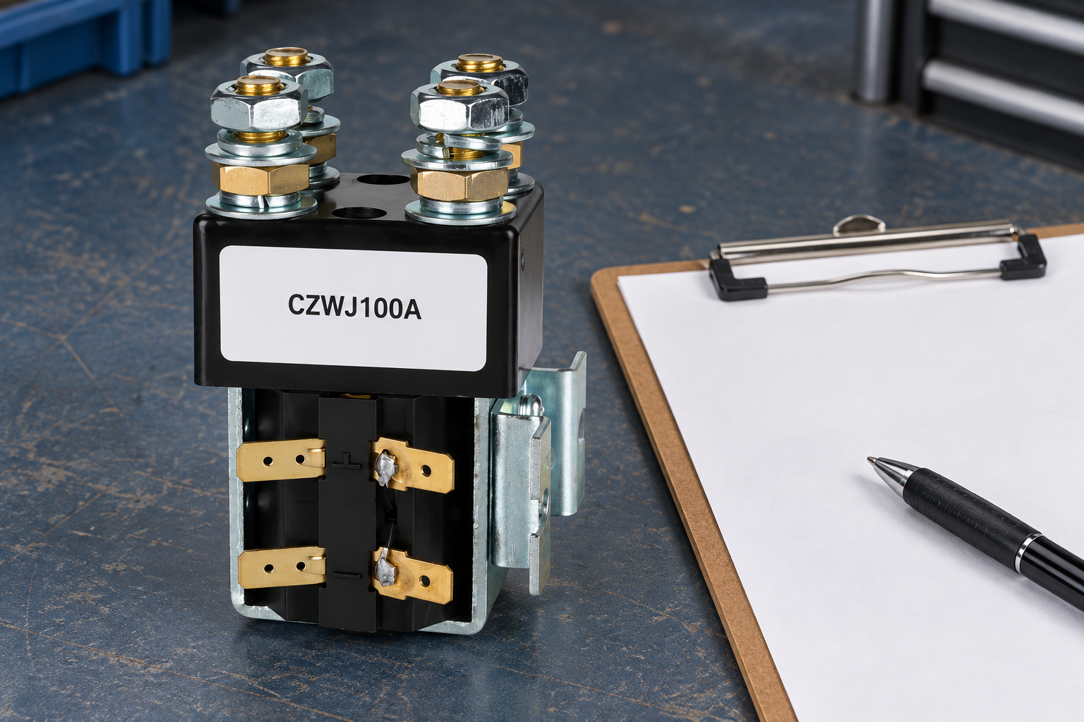
Prove the control interface and feedback behavior
Compare coil demand and operating range with the supply and controller output at the contactor terminals. Identify suppression, polarity-sensitive electronics and any separate driver. Verify that pickup and release behavior match the equipment sequence, including supply variation and recovery.
Record commanded state, coil condition, main-path response and auxiliary indication as separate observations. Auxiliary feedback alone may not prove every main contact has opened. The required diagnostic evidence depends on the actual mechanism and system function.
Avoid accepting an 80A replacement from an audible click or one continuity reading. Use appropriate controlled checks for arrangement and operation, then the agreed thermal and switching evidence for application acceptance. Fault demonstrations should only occur within an approved test plan and suitable facility, not an improvised machine trial.
Specify the complete architecture in the RFQ
Send the supplier the drawing showing the contactor relative to the drive and motor, the required pole form and normal state, voltage range, load profile, transitions and protection. Describe regenerative modes and feedback requirements where they apply. Include mounting and environment as well as the coil specification.
Ask for an exact supported variant and any restrictions on its use. If the supplier’s proposal changes pole form or control behavior, identify that change before the purchase is accepted. The quotation should answer the architecture requirement rather than merely offer a device with an 80A or larger current number.
For service replacements, retain the original approved sequence and acceptance record. A nominally stronger part may still be unsuitable when it creates incompatible states, changes release timing or omits needed feedback. Review those differences before releasing a repeat order.
Selection evidence checklist
| Review field | Information to provide | Acceptance boundary |
|---|---|---|
| Circuit position | Drive input versus direct motor path | Switching conditions differ |
| Contact diagram | Pole form, main states and auxiliary contacts | TwoNO does not establish reversal |
| Transitions | Stop, incompatible commands and recovery | Interlocks need documented evidence |
| Motor duty | Startup, stalled and repeated operation | No universal current multiplier |
| Current direction | Motoring and regenerative paths | Check documented direction limits |
| Control interface | Coil, driver, suppression and feedback | Validate the approved sequence |
This qualitative checklist organizes evidence; it does not state product ratings or universal acceptance limits. Numerical examples elsewhere are explicitly hypothetical.
Product information and related review tools
De CZWJ100A product information is the reference for the external construction shown. The pictured variant may have a different current class or contact arrangement from the requirement. It is not an automatic recommendation or a statement that every discussed duty is supported. Obtain the exact ordering code, drawing and applicable ratings before selection.
Gebruik de OEM specification evidence checklist to separate documented limits from unresolved assumptions. Complement the main-circuit review with coil voltage tolerance en mechanical versus electrical life. Those topics address distinct control and lifecycle questions rather than replacing this article’s assigned selection boundary.
Sources and safe validation
Scope references: IEC60947-4-1 contactor and motor-starter standard overview; U.S. electrical work-practice requirements. Apply relevant equipment requirements and approved manufacturer documentation. These links do not certify the illustrated product for a proposed duty. A commanded contact opening does not replace appropriate isolation and verification before servicing.
Educational contactor mechanism video
Electrician U explains the electromagnetic operating principle. This supports understanding of coil and contact operation, not a particular voltage, current, protection function or pictured variant’s qualification. The article’s selection evidence remains necessary whether or not the video is watched.

Veelgestelde vragen
Can twoNO poles reverse a motor by themselves?
No. Reversal requires an approved circuit architecture and control of incompatible states.
Is 80A running current enough to choose a motor contactor?
No. Include startup, stalled conditions, opening duty, repetition and the actual circuit position.
Can a drive-input contactor replace a motor-path contactor?
Not without a design review. The load conditions and assigned switching functions can differ.
Does auxiliary feedback prove every main pole opened?
Not automatically. Check the documented mechanism and the diagnostic evidence required by the equipment.





