DC contactor current rating margin is the difference between the required operating duty and a candidate’s supported carrying capability under the actual installation conditions. It is not a universal percentage to add to every load. Select margin only after defining continuous current, overload duration, ambient temperature, conductor arrangement and switching events. A larger nominal amperage may help a thermal decision, but it cannot compensate for unsupported DC voltage, making duty, breaking duty or protection coordination.
This guide explains how to record a justified margin without confusing a convenient sizing ratio with engineering approval. It focuses on the procurement calculation and its limits; separate derating guides address individual environmental effects in more detail.
Use comparable current definitions
Before dividing one current by another, establish what each value means. A measured average load, a maximum continuous demand and a short overload are different inputs. Likewise, a supplier’s current may be a continuous carry rating, an intermittent value or a value conditional on a specified installation.
Write the required current profile and the applicable documented capacity in adjacent fields. Include duration, repetition, ambient conditions and conductors with each. If the supplier value and equipment requirement are based on different conditions, the ratio is not yet a valid selection result.
State the main-circuit voltage and assigned contact transitions separately. This prevents a current margin calculation from being read as a complete contactor selection. Carrying current is only one of the application checks.
Define a transparent arithmetic convention
For a documented applicable carrying capacity C and required continuous current L, one possible reporting convention is headroom = C – L and headroom percentage = (C – L) / L × 100. This convention expresses headroom relative to the load. State the denominator because another reviewer might express unused capacity relative to the device rating.
As a hypothetical arithmetic example, assume an applicable carrying capacity of 400A and a continuous load of 320A. The headroom is 80A and 25% relative to the load. The same 80A is 20% of the assumed capacity. Both statements describe the same numbers using different denominators. Neither percentage is a recommended margin for an actual product.
The calculation requires a positive load value and a capacity valid for the installation. It is not meaningful to divide by zero, and it is misleading to insert an unadjusted catalog figure when the real enclosure is outside its conditions. Record uncertainties before reporting a precise percentage.
Keep a margin decision table
| Controleer item | Input to record | Evidence or decision needed |
|---|---|---|
| Required current | Maximum continuous load and time profile | Record measurement basis, operating states, overload duration and repetition; do not substitute a short observation for the design requirement. |
| Applicable capacity | Documented carrying value for this installation | Verify ambient, conductors, mounting and enclosure conditions before using the value in a headroom calculation. |
| Calculation convention | Capacity minus load, relative to stated denominator | State whether percentage is relative to load or capacity and retain units so two reviewers can reproduce the result. |
| Uncertainty | Instrument limits and incomplete operating observations | Resolve the measurement basis or use an accepted engineering allowance; avoid inventing a precise multiplier without evidence. |
| Future demand | Explicit planned load increase | Describe future current as a design input rather than concealing expansion inside an unexplained margin percentage. |
| Overload | Peak magnitude, duration and recovery | Request appropriate time-dependent guidance; average current or a continuous sizing ratio does not settle the overload question. |
| Independent switching | Voltage, closure transient and opening events | Review making and breaking duties separately, even when the closed-path carrying calculation shows substantial headroom. |
| Approval record | Evidence, owner and re-evaluation triggers | Save the documented capacity, current profile, assumptions and conditions so later substitutions or enclosure changes can be reviewed. |
Use the table to identify which facts support the calculation and which remain open. Each adjustment should have a documented basis. Where a factor is unknown, request evidence or plan an engineering evaluation rather than multiplying by an invented allowance.
Account for measurement uncertainty and demand changes
A current measurement should identify instrument, sampling method, operating state and observation period. A short observation may miss startup, charging or seasonal demand. The equipment designer should define a representative profile rather than simply selecting the highest value from an incomplete log.
Separate measurement uncertainty from expected future capacity. If the equipment is intended to support a future load increase, state that increase as a design requirement. Do not hide it inside an unexplained percentage. The supplier needs to understand which duty it is being asked to support.
Also identify tolerance in source voltage and load control. Some operating states can increase current even if nominal power is unchanged. Use the actual electrical design and documented control limits rather than assuming one catalog power figure determines every current condition.
Treat overload as a time-dependent requirement
A contactor with suitable continuous carrying capability still needs review for overload duration and repetition. Record the overload waveform or current blocks. Ask for the manufacturer’s relevant short-duration guidance and the recovery conditions between events.
Do not convert peak current to a continuous requirement using a simple duty-cycle average. Resistive heating depends on current squared and time, and the component’s thermal response matters. Where a model or test method is used, document its assumptions and let the responsible engineer assess applicability.
A useful illustration is P = I²R: if resistance remained constant, increasing current by 10% would increase resistive heating by 21%. Real resistance and heat transfer can vary with temperature and construction, so this arithmetic is a physical illustration rather than a product prediction.
Apply environmental evidence before adding margin
Record the temperature at the installed contactor and the enclosure arrangement. If a manufacturer’s rating depends on specified ambient conditions, request the applicable capacity for the actual conditions. Avoid applying both a supplier derating curve and an unrelated generic factor to the same effect.
Check altitude, ventilation and nearby heat sources where relevant. Each can affect a different part of the assessment. A larger current frame does not automatically correct insulation or clearance issues. Use the temperature derating guide en de altitude review guide as complementary questions for the specification.
Include connection conditions in the capacity value
Conductor size, busbar arrangement, terminal hardware and mounting can influence installed heat. Compare your proposed connections with the conditions supporting the rating. Ask for permitted torque and hardware from the exact drawing; a generic torque value is not reliable evidence.
Check whether the arrangement permits the expected conductor forces without twisting terminals. A thermally suitable frame can still be installed poorly. Keep conductor support and joint inspection on the acceptance checklist, and record changes made after a thermal evaluation.
Review switching independently of thermal headroom
A capacity ratio describes the closed path. Making and breaking duties require separate evidence at the relevant DC voltage and circuit characteristic. A device with substantial thermal headroom can still be unsuitable for opening an inductive current or closing onto an uncharged capacitor.
For converter systems, describe the precharge sequence and the current expected at normal opening. Also review failure and emergency states. The University of Texas capacitance explanation supplies background on stored charge, not a contactor qualification.
De IEC contactor standard publication record identifies a standards route. Its existence does not demonstrate that a particular device or sizing ratio meets an application. Require product-specific evidence for the exact ordering code.
Do not confuse margin with fault protection
Available fault current may exceed normal load by a large amount. A margin against continuous load is not a fault-clearing capability. Identify the fuse or breaker assigned to clear faults and the contactor’s documented role during that event.
Review coordination using the actual combination and circuit conditions. Do not assume that doubling a frame rating doubles fault performance or service life. Document the post-fault inspection decision and any required replacement conditions.
Verify the result in an installed review
Agree on a qualified test plan covering the current profile, ambient measurement, enclosure state, terminals and measurement points. Record stabilization and acceptance criteria from the applicable engineering procedure. Use isolated checks first and appropriate facilities for energized work.
A sizing calculation is not authorization to perform an unsafe test or work on energized terminals.
Record the rationale in the purchase specification
Save the required load profile, applicable candidate capacity, document references, calculation convention and unresolved conditions. State who accepted the evidence and which changes trigger re-evaluation. This makes the decision reproducible when a supplier offers an alternative.
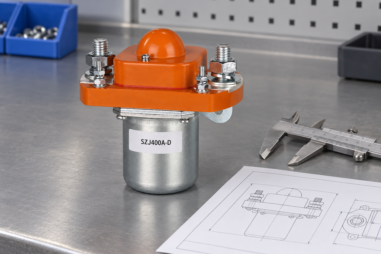
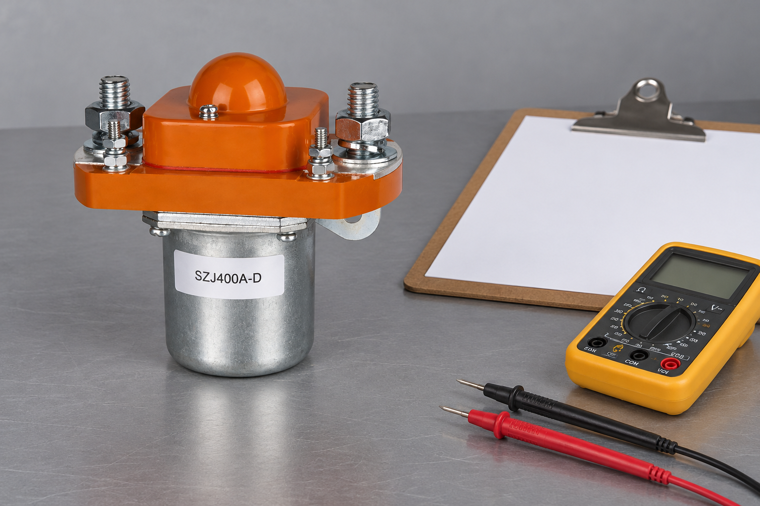
De SZJ400A-D Normaal Open DC-contactor pictured here illustrates physical construction only. Neither its model name nor the photograph supplies the capacity value for your calculation. Ask Sayoon for the exact supported variant and its installation evidence. The DC contactor current-selection hub connects this current assessment to the remaining selection checks.
Educational video: the contact mechanism
This educational explanation of contactor operation helps distinguish the control coil from the main contacts. It does not recommend a sizing percentage or qualify the illustrated device for a calculated margin.

Watch the Electrician U educational explanation on YouTube.
Veelgestelde vragen
What percentage current margin should I use?
There is no universal percentage. Use the actual load profile and the candidate capacity supported under the installation conditions, then document the engineering rationale.
How can I calculate headroom?
One stated convention is capacity minus required load, divided by required load. The inputs must be comparable and the load must be positive.
Can a larger current rating compensate for unsupported breaking duty?
No. Carrying headroom and making or breaking qualification are separate requirements.
Does the 400A and 320A example recommend a product?
No. It is hypothetical arithmetic illustrating two percentage conventions, not a product rating or application approval.





