PWM contactor coil control can reduce a compatible DC contactor coil’s hold-stage power by applying full, approved pickup drive first and then regulating current after the contactor has closed. It is niet permission to apply an arbitrary pulse width, frequency, or voltage to every contactor. The exact coil, integrated electronics, allowable drive waveform, pickup time, minimum hold current, temperature range, and required release time must be confirmed before using an external PWM driver. If the manufacturer has not approved PWM for the selected coil option, use its specified control supply instead of experimenting on the installed system.
Understand pickup, hold, and release as separate phases
A contactor coil must first establish enough magnetic force to move the armature and close the contacts. This pickup event may demand a different current from the amount needed to keep the armature seated. Once fully closed, some designs can remain engaged with a lower regulated current, reducing coil heating and control-supply load. At release, coil current must decay sufficiently for the armature to open. These are three distinct phases, and one generic duty-cycle setting cannot describe all three.
A typical external peak-and-hold strategy therefore begins with an approved pickup interval and then changes to a controlled hold interval. The changeover can be based on time, measured current, position feedback, or a device-specific controller. Each approach has limits. A fixed timer may switch too early under low supply or cold conditions, while current alone does not prove the main contacts reached their intended position. Texas Instruments’ solenoid-drive application note explains the general peak-and-hold principle and the relationship between PWM and coil-current regulation. A contactor must still be checked with its own data; a valve-solenoid example is not a contactor specification.
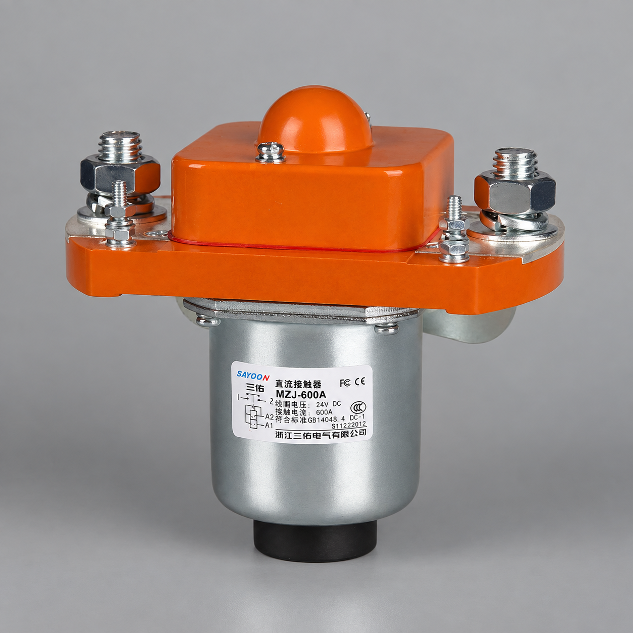
Some DC contactors already include an economizer or electronic input stage. Applying PWM to the external input of such a device may interfere with its own startup logic, diagnostic circuit, or internal switch. The purchase code and drawing matter more than the product-family name. The image below identifies one actual Sayoon product; it is not a claim that every version of the model accepts external PWM.
Why duty cycle alone is not a reliable design rule
Duty cycle describes the fraction of each switching period for which the driver applies its on-state. It does not directly specify coil current. The current depends on supply voltage, coil resistance and inductance, current already circulating at the beginning of the period, switch voltage drop, recirculation path, frequency, temperature, and the armature’s position. Two drivers at the same nominal duty cycle can therefore produce different peak, ripple, and average currents. A hot coil may also behave differently from a cold one.
Do not infer a “safe 50% duty cycle” from a separate product, even if both have the same nominal coil voltage. The first task is to obtain the allowed pickup and hold current or voltage envelope for the exact coil. The second is to choose a driver capable of measuring or otherwise reliably controlling that envelope. A current-regulated approach can compensate for some supply and resistance changes, but the sense circuit, filtering, response speed, and fault detection then become part of the design. TI’s solenoid current-sense note illustrates why a PWM current waveform must be measured with a suitable sensing arrangement rather than inferred from duty cycle alone.
Frequency introduces another trade-off. A low frequency can create substantial current ripple and audible or mechanical effects; a high frequency can increase switching losses, electromagnetic emissions, and driver heating. Neither a low nor a high number is universally correct. The allowable range comes from the coil, driver, suppression circuit, and system-level electromagnetic compatibility requirements. A controller output labeled “PWM capable” is not necessarily rated to switch the coil directly.
A decision table for an external PWM proposal
| Question | Evidence needed before PWM | What to test on the actual assembly |
|---|---|---|
| Is external PWM permitted? | Exact coil option and manufacturer-approved input waveform | Input behavior at startup, hold, command-off, and restart |
| Will pickup remain reliable? | Pickup current or voltage envelope over supply and temperature | Worst-case pickup time and contact closure |
| Will hold remain stable? | Minimum hold requirement and expected vibration environment | Current ripple, chatter, coil temperature, and auxiliary feedback |
| Will the driver survive? | Peak and continuous current, switching loss, thermal and transient limits | Driver temperature and voltage spikes at representative duty |
| Will it release in time? | Allowed discharge path and stop-time requirement | Coil-current decay and actual contact opening distribution |
| Will diagnostics still work? | Open-load, short, feedback and safety-system assumptions | Command/feedback disagreement and defined fault states |
This is a verification checklist, not a table of recommended electrical settings. Without coil-specific limits, measured performance cannot be judged against an acceptance criterion. If the supplier cannot confirm external PWM, record that limitation and choose a compatible coil or a contactor variant with a specified integrated economizer rather than inventing a setting.
Design the power stage for the complete waveform
The driver must support both the initial pickup event and the repetitive hold-stage switching. Evaluate transistor or integrated-driver current rating, voltage rating, junction or case temperature, thermal path, short-circuit behavior, and switching losses. Account for simultaneous coils on a shared supply, wiring drop, and input filtering. An output that survives one bench cycle may overheat after sustained operation in an enclosure at elevated ambient temperature. Likewise, a control supply sized only from average hold current may collapse during simultaneous pickup.
Choose high-side or low-side switching deliberately and verify the return path. The separate high-side versus low-side driver guide addresses switch placement and fault behavior. For PLC control, our PLC-spooldrive-geleider explains why a logic output may need an interposing driver; the PLC’s ability to generate PWM does not establish that its output can carry the coil current or turn-off energy.
Measure at the coil terminals, not just at the power supply. Use a current probe or appropriate isolated current measurement so the full pickup waveform, PWM ripple, hold level, and decay can be seen. Capture driver voltage at turn-off with instruments rated for the circuit. Ensure a measurement lead does not unintentionally bridge isolated domains or expose personnel to the separate main DC circuit. The main contacts and the control coil are different circuits even when packaged in one device.
Recirculation, suppression, and release are linked
During each PWM off interval, inductive coil current needs a path. A diode or other recirculation network can maintain current between pulses; the exact path determines current ripple, voltage stress, and heat distribution. At final command-off, that same path may keep current flowing and delay release. A clamp selected only to make the driver voltage look quiet can therefore change the machine’s stop behavior. TI’s inductive-load switching note discusses the relationship between clamp voltage and current discharge time.
Do not add a generic flyback diode across a coil that already has internal electronics without the manufacturer confirming compatibility. A diode can also be inappropriate where a faster release is required and a different rated clamp has been specified. Conversely, removing suppression to accelerate release can exceed the driver voltage rating or create electromagnetic interference. The correct path must be designed as part of the driver and verified at the worst credible supply and temperature conditions. The dedicated contactor timing guide separates electrical command changes from physical contact timing.
When PWM stops, explicitly define whether the output immediately disables, ramps down, transitions to a different clamp, or relies on an internal economizer. A software timer is not the same as measured contact release. Capture multiple cycles so dispersion is visible; one nominal waveform is not proof of a reliable stop time.
Build a commissioning test that can fail usefully
- Record the exact coil and driver part numbers, revisions, approved input waveform, connector polarity, internal suppression, and pickup/hold limits.
- Define acceptance criteria for pickup time, stable hold, release time, current ripple, temperature, transient voltage, and feedback response before testing.
- Test low and high control-supply limits, cold and hot coil conditions, the intended enclosure temperature, and representative switching frequency.
- Capture command, coil-terminal voltage, coil current, auxiliary feedback, and relevant main-circuit state on a common time base.
- Look for chatter, unintended opening, delayed release, driver thermal shutdown, restart surprises, and electromagnetic interference with neighboring controls.
- Test defined supply-loss, open-wire, short-circuit, and control-reset scenarios using approved safe procedures. Do not create hazardous faults on an energized high-power assembly merely to complete a checklist.
- Freeze the validated settings and preserve the waveforms, drawings, and replacement-part identities. Revalidate after changing a coil option, driver, clamp, supply, or software timing.
Feedback matters especially where a hold current is close to the mechanical dropout boundary. An auxiliary signal can reveal command/position disagreement, but it is not proof that a high-voltage main path is fully isolated. Apply the machine’s safety concept and energy-isolation procedure independently of the PWM controller. For related current and heat estimation, read our coil power consumption guide.
Connect PWM planning to a product enquiry
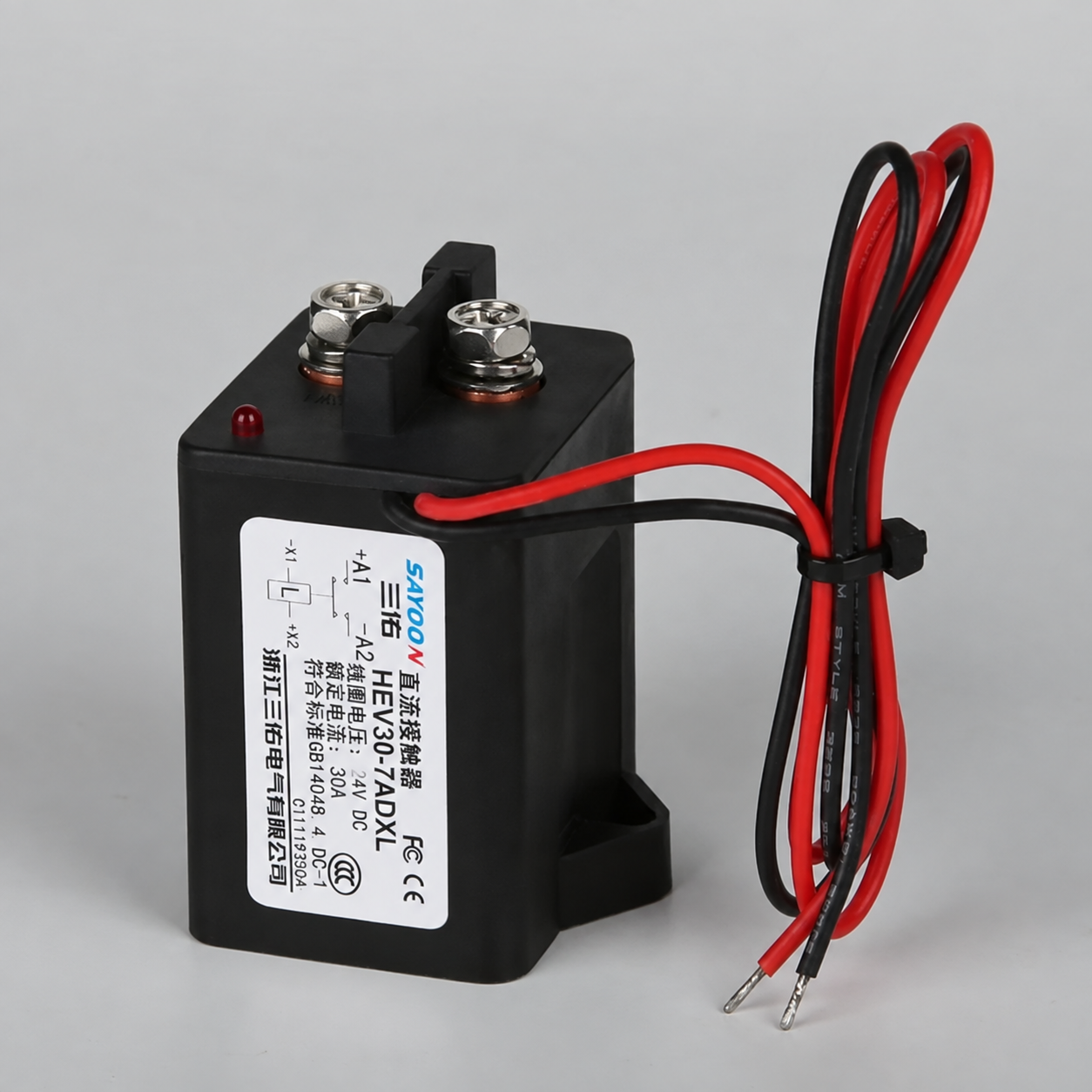
De Sayoon MZJ-100D product page identifies one product family option, but a pictured label does not constitute approval for external PWM. Ask the supplier for the exact ordered coil variant, input range, pickup and hold behavior, built-in economizer or clamp, maximum switching and thermal limits, and the approved application drawing. For the wider device choice, consult the Selectiehandleiding voor DC-relais before optimizing coil power. A well-defined RFQ also includes main-circuit voltage and load type, ambient conditions, available control supply, expected duty, target release time, feedback requirements, and applicable safety requirements.
Where no model-specific PWM data exists, use the product’s specified fixed control supply and leave the external PWM idea out of the production design. The energy saving from an unverified economizer is not worth a contactor that chatters, fails to pull in, or releases unpredictably.
Video: understanding pulse-width modulation
Afrotechmods explains the pulse-width modulation principle visually. It is background education only; its examples do not provide duty-cycle or frequency values for a Sayoon contactor coil.
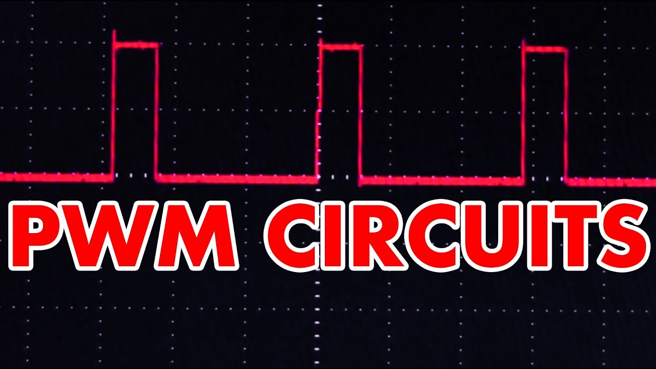
Watch Afrotechmods’ PWM tutorial on YouTube.
Veelgestelde vragen
Can every DC contactor coil use PWM?
No. External PWM requires approval for the exact coil option and any internal electronics. Otherwise use the specified control supply.
What duty cycle should be used for hold?
There is no universal value. Determine the permitted hold-current envelope from the manufacturer, then measure current and stable operation over supply, temperature, and vibration conditions.
Does PWM automatically speed up release?
No. The recirculation and final turn-off clamp control current decay. Some arrangements delay release despite reducing hold-stage power.
Can a PLC PWM output connect directly to the coil?
Only if the exact output is rated for pickup, continuous current, switching losses, turn-off energy, and the coil’s approved waveform. Otherwise use a suitable interface driver.





