Быстрый ответ: Use the contactor for normal reversible control and the pyrofuse as an independent last-resort interruption when the fault energy or crash timing exceeds the contactor’s safe breaking duty. A pyrofuse does not replace a contactor’s isolation and precharge functions, and a contactor does not guarantee interruption of every bolted fault. The battery safety concept should state which device acts first and how the remaining voltage is removed.
An ev contactor pyro fuse strategy assigns different jobs to two different devices. Contactors provide repeated, commanded switching for start-up, charging, service, and normal shutdown. A pyrofuse is a one-time, fast disconnect that can open a high-current path after a crash or severe electrical fault. They must be coordinated with fuses, current sensing, HVIL, discharge, and a replacement procedure.
At-a-glance design map
| Element | What it does | Selection or diagnostic focus |
|---|---|---|
| Главный контактор | Repeatable make/open under approved DC duty | Normal switching, precharge coordination, service isolation |
| Pyrofuse | One-time forced interruption | Crash or severe fault where speed and fault energy dominate |
| Fuse/current limiter | Limits prospective short-circuit energy | Coordinates with contactor and pyrofuse clearing |
| HVIL and discharge | Prevent access and remove stored energy | Verify the pack is safe after the interruption |
Ссылка на продукт и его область применения
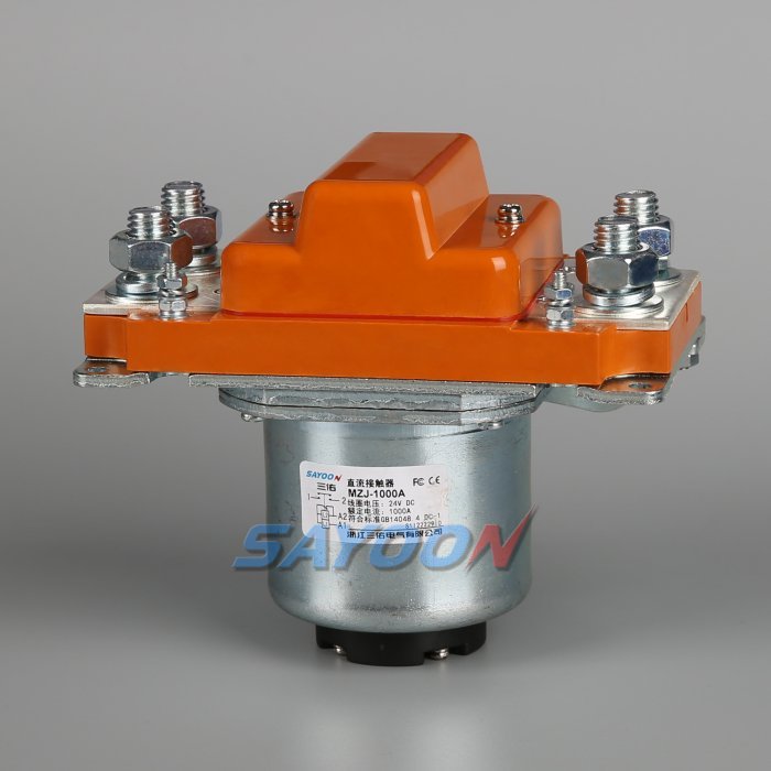
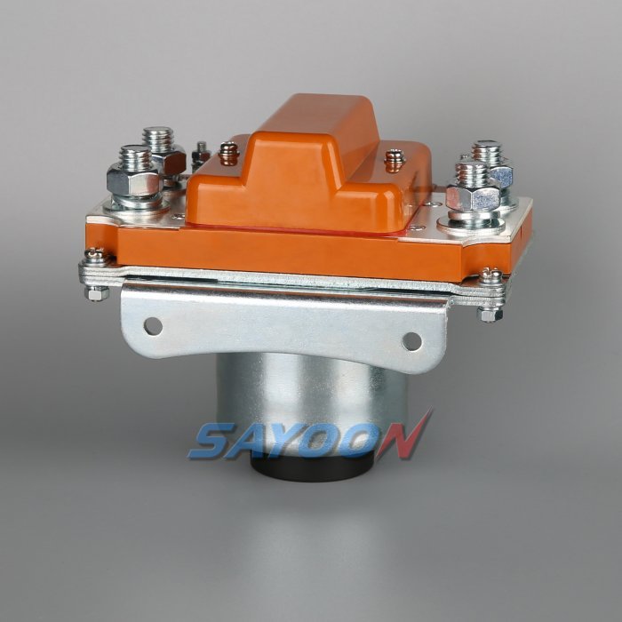
The MZJ-1000A normally-open DC contactor shown in this article is a real Sayoon product reference. See the MZJ-1000A normally-open DC contactor product page и сеть высоконапряжных контакторов постоянного тока for the family context. The image does not replace a model-specific drawing review; voltage, coil, current, insulation, duty, and mounting must be confirmed for the application.
Different devices, different failure assumptions
A contactor has moving contacts, a coil, and an arc-control system. It can be commanded many times, but its interruption ability depends on DC voltage, current, polarity, load inductance, and contact wear. A pyrofuse uses a trigger and a physical element to create a permanent open circuit. It is fast and powerful within its rated envelope, but it must be replaced and its status must be diagnosed.
The two devices are complementary. A pyrofuse cannot perform a controlled precharge or a normal key-off cycle. A contactor may not clear a short circuit quickly enough to protect the pack or vehicle harness. The design should avoid asking either device to perform the other device’s job.
Normal start, stop and crash sequence
During a normal start, check HVIL and isolation, use the precharge path, close the main contactors after the DC link reaches its threshold, and monitor feedback. During a normal stop, remove torque, open the main contactors at an approved current, and discharge the load-side bus. During a crash or severe fault, the crash controller may command the pyrofuse and the contactors together or in a defined order, while the BMS records the trigger and blocks re-energization.
The exact order depends on the electrical architecture. A pyrofuse trigger should not be delayed by a software path that can be lost in the same crash. Conversely, a contactor should not be opened under a current higher than its approved breaking duty merely because a pyrofuse is present.
Interruption and coordination
Specify prospective short-circuit current, battery internal resistance, pack voltage, inductance, fuse clearing time, contactor opening time, and the pyrofuse interrupt rating. Coordination means the devices share fault energy in a predictable way and the surviving insulation and busbars remain within limits. A table of nominal currents cannot establish this; use measured or qualified waveforms and the manufacturer’s application data.
The MZJ-1000A reference shown here is a product example, not an automatic crash disconnect approval. Send the maximum battery voltage, current trace, trigger source, enclosure temperature, and required clearing time with an RFQ so the model and protection network can be reviewed together.
Diagnostics after a pyrofuse event
After firing, the pack should report a latched event, isolate the high-voltage system, and provide service personnel with a clear replacement and inspection procedure. Verify pyrofuse continuity only with an approved low-energy method; never inject a test current that could trigger or heat the device. Inspect the contactors, fuse, busbar, precharge resistor, connectors, and crash-signal wiring for secondary damage.
A contactor auxiliary contact can still appear open after a pyrofuse event, but that does not prove the pyrofuse has interrupted the intended conductor. Use pack and load-side voltage measurements, a documented discharge path, and the device’s own status circuit where available.
HVIL, isolation and stored energy
A crash disconnect is not complete until stored energy is controlled. HVIL should block reclose and communicate the open path. Isolation monitoring should check for chassis leakage before and after the event. The DC-link capacitors still require a discharge path and a measured threshold before a technician touches the bus. The service manual should state wait times, probe points, and PPE.
Use the OSHA hazardous-energy and electrical-work practice framework together with the vehicle maker’s instructions. Treat an apparently open contactor as energized until the measurement and discharge checks prove otherwise.
Thermal and mechanical installation
Contactors and pyrofuses generate heat, magnetic forces, and vibration loads. Provide busbar support so a crash or short-circuit force is not transferred into the terminals. Keep clearances around the arc-control region, route trigger and coil wires separately where required, and derate continuous current for enclosure temperature. Repeated charging cycles can heat contactors even when a crash event never occurs.
Record mounting orientation, torque, conductor size, and sealing in the production drawing. A correct device installed with a loose busbar or inadequate cooling can fail earlier than a smaller device installed within its qualified conditions.
Verification and acceptance tests
Verify normal switching with the specified load profile, precharge timing, contactor feedback, and discharge. Verify the fault path using a qualified test plan or manufacturer evidence; do not improvise a short-circuit test on a production pack. Exercise the crash signal path with a safe simulator, confirm that the pyrofuse trigger is latched, and verify that software cannot command a reclose after the event.
Retain the waveform, trigger timestamp, device serial or lot, temperature, and inspection photographs. A clear record lets the OEM distinguish a valid safety event from a wiring or driver fault and supports controlled service replacement.
Acceptance record for the engineering team
Before approving this ev contactor pyro fuse decision, create one controlled record that can be read by the design engineer, test engineer, production team, and service technician. List the exact part number and coil option, drawing revision, terminal labels, bus voltage range, current waveform or duty profile, ambient and enclosure temperatures, mounting orientation, conductor size, terminal torque, driver and suppression details, auxiliary logic, HVIL state, measurement instruments, calibration dates, and the pass/fail thresholds. Separate catalogue values from measured values and identify every assumption. If a value is not available, mark it as an open engineering action instead of filling the gap with a typical number.
Run the sequence at the boundaries that matter: minimum and maximum low-voltage supply, cold and warm equipment, the longest approved harness, repeated cycles, and the abnormal state that the safety concept names. Capture command, coil current, feedback, pack voltage, load-side voltage, and fault flags on one time base. After a failed event, stop automatic retries, isolate stored energy, and preserve the first-fault data. A later successful cycle does not erase evidence of a welded contact, slow release, intermittent interlock, or driver protection event. Release the product only when the complete record is reviewed against the current data sheet and vehicle-level requirements. Include photographs of the terminal layout and probe locations, the software build and calibration state, and a short explanation of why the chosen threshold is safe. This makes the result repeatable when a replacement sample, new harness, or firmware revision is introduced.
Related engineering guidance
Используйте Руководство по выбору контакторов постоянного тока for the broader sizing workflow, the safe contactor test guide for isolation and measurement, and the Руководство по времени открытия и закрытия when setting diagnostic windows. For PLC-connected control logic, see the Руководство по управлению роторным клапаном с помощью ПЛК. These internal links support the decision without replacing the device data sheet or the vehicle safety procedure.
Обучающее видео
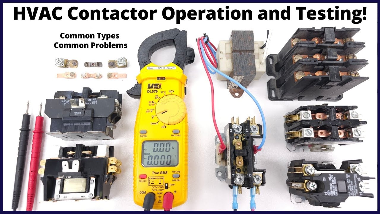
This neutral training video is included for visual context. It is not a product endorsement and the written, model-specific requirements above control the engineering decision.
Посмотрите обучающее видео на YouTube.
Часто задаваемые вопросы
What is the first check for ev contactor pyro fuse?
Confirm the exact command, supply, coil option, and safe measurement points before energizing anything. Then compare the expected feedback and bus-voltage response with the approved sequence.
Can auxiliary feedback prove the main contacts are healthy?
No. It reports mechanism position within its own limits. Combine it with load-side voltage, timing, and the documented circuit state.
Can I use a generic contactor driver or suppression diode?
Only after the coil, driver, polarity, release time, EMC, and protection behavior are approved together. A generic change can create slow release or false diagnostics.
Что должно быть включено в запрос котировок (RFQ)?
Provide voltage, current waveform, switching duty, temperature, mounting, coil voltage, suppression, feedback, insulation, life, and the required drawings and test evidence.
Sources and standards context
- NHTSA electric-vehicle safety information
- Texas Instruments high-voltage contactor driving note
- Требования OSHA по управлению опасной энергией
Standards, safety rules, and supplier ratings change by market and product revision. Use the current edition adopted by the project and obtain the full requirements through the responsible engineering and compliance process.





