Подключение контактора A1 A2 — это этап идентификации цепи катушки: перед подачей питания проверьте обозначения клемм, номинальное напряжение катушки, примечания по полярности (если указаны), тип разъема и цепь управления, при этом силовее полюсы рассматриваются на отдельной схеме. Используйте это, чтобы разделять проверки клемм катушек и работы с кабелями силовых полюсов на панелях постоянного тока. Это контрольный список для команд производителей оригинального оборудования (OEM) и сборщиков панелей, а не расчет размеров или утверждение для contactor-a1-a2-wiring-dc-coil-terminals-panel-builders.
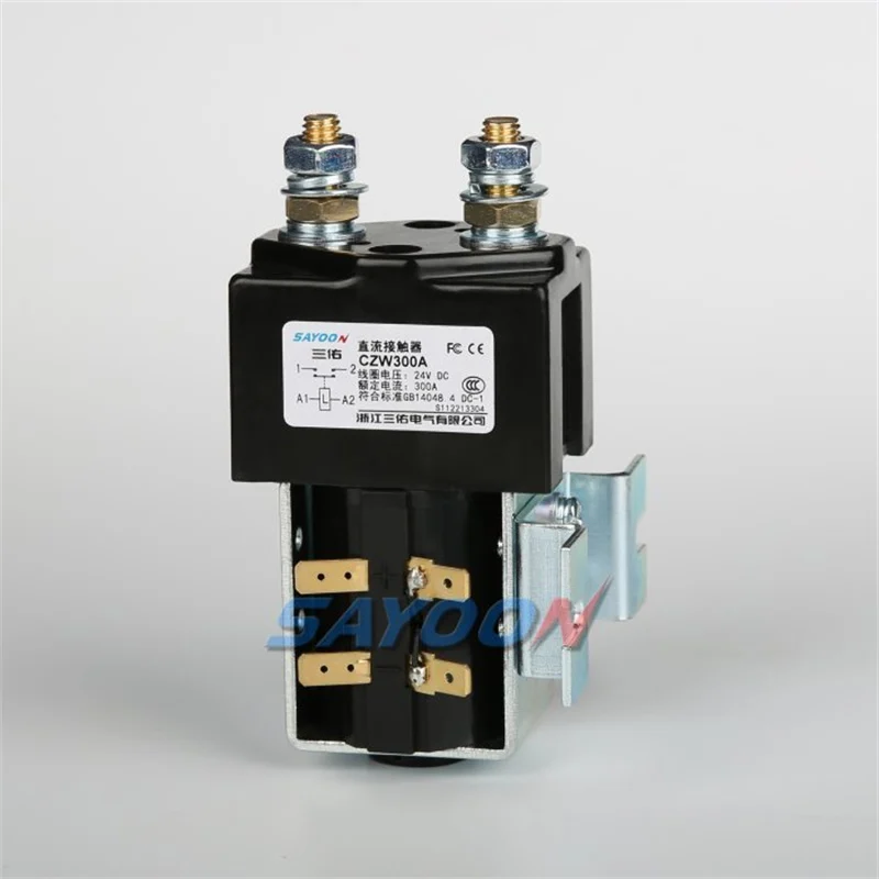
Часть 1. Рассматривайте A1/A2 как маркировку катушки, а не полюса нагрузки
На многих промышленных контакторах клеммы A1 и A2 обозначают цепь катушки. Силовые полюсы имеют отдельные обозначения. Обзоры монтажа контакторов по A1 и A2 оказываются неудачными, когда специалисты подают питание на клеммы катушки, используя методы работы с силевыми кабелями, или когда они предполагают, что привычки соблюдения полярности катушек переменного тока применимы без изменений к любому даташиту катушки постоянного тока.
Команды, ищущие подключение контактора а1 а2 обычно нужен чек-лист проекта, а не слоган для каталога.
Проверка катушек продвигается быстрее, когда номера ревизии чертежа и разъема жгута проводов передаются вместе с кодом модели контактора.
Часть 2. Проверьте номинальное напряжение катушки перед подключением проводников
Проверьте список номинальных напряжений катушки на установленной или предлагаемой модели. Чертеж с указанием 24 В постоянного тока не дает права использовать корпус катушки на 110 В. Если заводская табличка и техническое описание расходятся с чертежом, остановитесь и оформите запрос на изменение документации — не ‘пробуйте’ подавать другое напряжение.
| Проверить | Условие прохождения | Отправить с цитатой |
|---|---|---|
| Карта маркировки рулонов | A1/A2 определены отдельно от силовых полюсов | Фотография терминала + рисунок |
| Напряжение катушки | Чертеж соответствует техническому описанию/паспорту | Требуемое значение США |
| Тип терминала | Жгут соответствует примечанию к разъему в техническом описании | Обозначение деталей разъема |
| Качество поставок | Измерено на катушке по методике | Записка с показаниями счетчика |
| Удержание нот | Импульс/полярность копируются при использовании удерживающей катушки | Заметка о времени водителя |
Часть 3. Проверьте тип клеммы и примечания к соединителю
Технические описания контакторов постоянного тока SAYOON часто указывают тип выводов катушки, например, разъемы 6,3 мм для конкретных моделей. Подберите клеммы жгута в соответствии с этим примечанием. Изогнутые язычки, наконечники несоответствующего размера и плавающие перемычки являются распространенными дефектами на местах, которые впоследствии выглядят как отказ катушки.
Важно: Не подключайте проводники катушки до тех пор, пока напряжение $U_s$ на чертеже не совпадет с паспортными данными и заводской табличкой установленной модели.
Часть 4. Отделите качество питания цепей управления от вины самого контактора
Пониженное напряжение, шумные источники питания и общие возвратные цепи могут препятствовать срабатыванию или вызывать дребезг. Измерьте напряжение питания на выводах катушки под нагрузкой, определенной процедурой проекта. Замена контактора без подтверждения проблем с питанием приводит к перерасходу устройств и скрывает истинную неисправность.
Часть 5. Оставлять примечания об импульсах удерживающей катушки видимыми при использовании
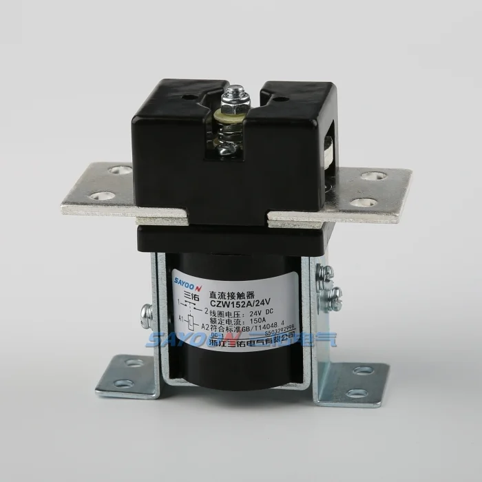
Модели с магнитным удержанием могут требовать указаний по длительности импульса и полярности, в отличие от катушек непрерывного действия. Если на панели используется удерживающая катушка, перенесите эти ограничения из технического описания в описание системы управления. Предположение о непрерывном напряжении 24 В для катушки с импульсно-удерживающим действием является проектной ошибкой, а не предпочтением при монтаже.
Часть 6. Маршруты изделий после документирования змеевика
Обсуждайте магнитные удерживающие пути CZW (нормально разомкнутые) или CZW-K только после того, как указаны напряжение катушки и тип клемм. Не переносите допущения о подключении катушек контакторов переменного тока на катушку постоянного тока без проверки полярности и номинального напряжения по техническому описанию.
| Ситуация | Маршрут САYOON | Почему это обсуждается |
|---|---|---|
| Непрерывный путь катушки НО | CZW100A / CZW400A | Проверка клеммы стандартного нормально разомкнутого (НР) реле |
| Панель катушки держателя | Семейство CZW50A-K | Применяются ноты пульса и удержания |
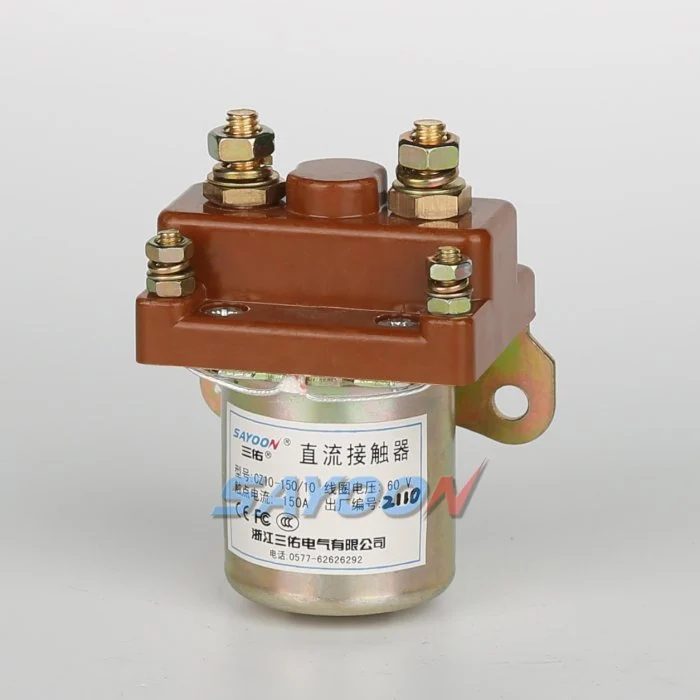
Маршруты продукции после документирования исходных данных:
- Нормально разомкнутый контактёр постоянного тока CZW100A — проверка типа клемм катушки после поставки задокументирована.
- Контактор постоянного тока CZW400A нормально разомкнутый — больший ток в цепи нормально разомкнутого контакта (NO) согласно примечаниям к катушке в техническом описании.
- Магнитный удерживающий контактор постоянного тока CZW50A-K — обсуждение выводов удерживающей катушки применительно к импульсным характеристикам.
После проверок А1/А2 откройте Серия CZW Контактор DC для семейного контекста, или связаться с SAYOON с выносками Us и разъемов.
По теме: Серия CZW Контактор DC; Пошаговое руководство по подключению базового пускателя; Руководство по подключению контактора с катушкой 120В.
Часть 7. Граница подгонки для обзоров разводки катушек
Границы применимости: идентификация клемм катушки постоянного тока и проверка цепи питания управления; это не разрешение на выполнение монтажа под напряжением, не список уставки и не замена проектной документации. Эта страница не дает разрешения на работу с панелью под напряжением и не заменяет порядок действий ответственного электрика.
ЧЗВ
Обычно маркировка контактов A1 и A2 на контакторе означает клеммы катушки управления этого устройства.
Обычно это относится к отдельному определению и подключению выводов цепи катушки от силовых полюсов в соответствии с техническим описанием модели и проектной документацией.
Всегда ли клеммы A1/A2 являются клеммами катушки постоянного тока?
Правила маркировки зависят от семейства моделей. Всегда сверяйтесь с техническим описанием и заводской табличкой установленного агрегата.
Что следует измерить, прежде чем обвинять катушку?
Подача питания на катушку на клеммах в соответствии с процедурой проекта, а также целостность разъема и правильное напряжение Us.
Как удерживающие катушки влияют на анализ схемы соединений?
Примечания о длительности импульса и полярности могут применяться; предположения о непрерывном возбуждении могут быть ошибочными.
Что должно содержаться в запросе предложений (RFQ) или извещении об изменении конструкции (ECO) на намотку катушек?
Требуемые США, тип клеммы, удержание по сравнению с непрерывным режимом, обозначения разъемов жгута проводов и ревизия чертежа.
Разрешает ли эта страница проведение работ на токоведущих частях под напряжением?
Нет. Работы под напряжением выполняются в соответствии с правилами техники безопасности объекта и ответственными лицами.





