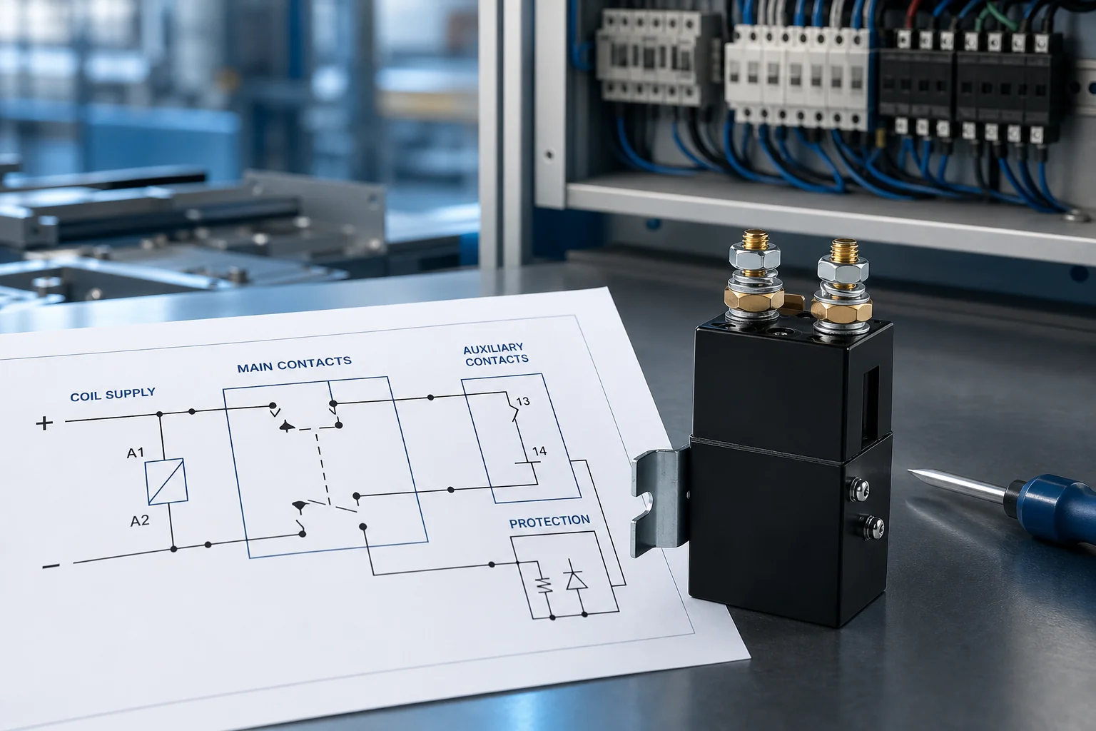
Before panel review, a usable dc contactor diagram must make six items checkable on one drawing package: coil supply, contact form, protection, polarity, auxiliary feedback, and clear labeling.
This article walks those blocks in review order. It stays on drawing completeness for DC panels, not symbol literacy and not a full AC versus DC theory comparison.
What a review-ready DC contactor diagram must prove
It must prove that a reviewer can verify coil, power path, protection, polarity, feedback, and labels without guessing from habit.
A forklift charger panel often fails FAT when the sheet shows only two main studs. The missing control-coil circuit is discovered only after someone applies control power and nothing moves.
Treat the drawing as two linked circuits. The power path carries DC load current through the main contacts. The control path energizes the contactor coil and any auxiliary logic tied to that motion.
| Review block | Must appear on the diagram | Why the reviewer needs it |
|---|---|---|
| Coil supply | Voltage, terminal marks, polarity if required | Confirms the coil can pick up on the real control bus |
| Форма обратной связи | NO or NC resting state for the main path | Matches the panel’s expected rest condition |
| Protection | Branch device and any coil suppressor path | Shows how faults and Back EMF are handled |
| Polarity | Load +/− orientation and coil +/− when used | Prevents reverse-wire damage or silent non-operation |
| Auxiliary feedback | Aux NO/NC, terminals, destination | Gives status or interlock beyond the coil command |
| Labeling | Wire IDs, terminal IDs, document references | Makes the sheet auditable against the OEM drawing |
Independent wiring education makes the same split: power terminals versus coil terminals such as A1/A2, with auxiliaries for seal-in or PLC feedback (contactor wiring diagram overview).
Coil supply details the diagram must show
Show the coil rated voltage, the exact terminals, and polarity marks whenever the selected coil is polarized.
The contactor coil is the electromagnet that actuates the contacts when control voltage is applied. In plain terms, it is the low-power circuit that tells the contactor to close or open.
Coil voltage can differ from the power-circuit voltage on the same device. Write the control voltage on the drawing next to the coil symbol, and keep it aligned with the nameplate option the buyer ordered.
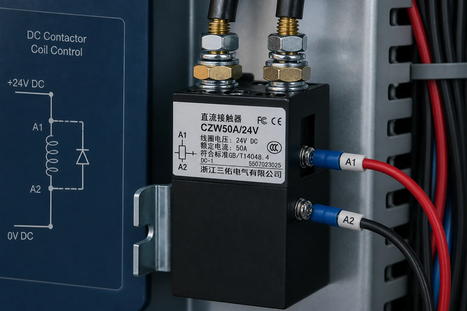
When a dual-coil, PWM, or economizer coil is polarized, reverse leads can block pick-up or damage the device. Contactor coil polarity belongs on the sheet the same way the OEM marks the leads.
From the field: Builders often separate contact polarity from coil polarity too late. One DIY EV thread started with “contacts are polarized… but what about the coil leads?” and resolved only after the side view showed black = − coil and red = + coil on an economizer unit (DIY Electric Car Forums).
If the model offers a suppressor-diode option, note that option on the coil callout so the control designer does not add a conflicting external path later.
Contact form on the power path
Label the main-path resting state as normally open or normally closed so the panel logic matches the hardware.
Contact form is the resting state of the power path with the coil de-energized. In plain language, it answers whether the path starts open or closed before control power is applied.
A communication-power board that expects an open rest path needs a 1 NO device drawn as open at rest. A fail-safe cutoff that must conduct until the coil pulls in needs a 1 NC path drawn as closed at rest.
SAYOON’s CZW50A normally open DC contactor lists contact form 1 НЕТ, with published wiring and installation diagrams on that product page. SAYOON’s SZJB300A-D normally closed DC contactor lists contact form 1 NC for drawings that require a normally closed main path after datasheet review.
Do not let a familiar housing replace the contact-form note. Two look-alike bodies can rest in opposite states. Write the contact form beside the main-path symbol, then repeat it in the BOM line so purchasing and wiring use the same resting-state language.
Protection and suppression callouts
Draw the branch protection that feeds the power path and any coil suppression path the design actually uses.
Branch protection belongs on the sheet as a fuse, breaker, or other listed device upstream of the contactor power terminals. Reviewers need that mark to confirm fault energy is limited before the first power-up.
Coil suppression clamps Back EMF when the coil drops out. A flywheel diode protects the driver, yet it also polarizes the coil connections and can slow contact opening compared with an unsuppressed coil.
If suppression is integral to the contactor, still call it out. Reviewers then know not to stack a second diode that fights the OEM timing or polarity rules.
Capacitive DC loads may need a pre-charge path on the same drawing package. Without it, the main contacts can see a surge that the rest of the schematic never warned about.
Load polarity and coil polarity as separate checks
Treat power-terminal +/− orientation and coil +/− orientation as two different drawing checks.
Load-path polarity is the required orientation of marked power terminals relative to source and load. In plain terms, it is which way the +/− power studs must face so arc control works as rated.
Community questions show how easy it is to treat a DC contactor like an unpolarized mechanical switch until the datasheet mentions reverse current limits. Put the source and load arrows on the drawing before the panel is built.
| Check | What to mark | Typical failure if omitted |
|---|---|---|
| Coil polarity | Coil +/− or red/black lead map | Contactor never picks up, or economizer electronics are stressed |
| Load-path polarity | Power terminal +/− facing source/load | Arc performance and interrupt life diverge from the rated direction |
| Shared note | “Confirm OEM marks for this model” | Field wiring follows habit instead of the selected datasheet |
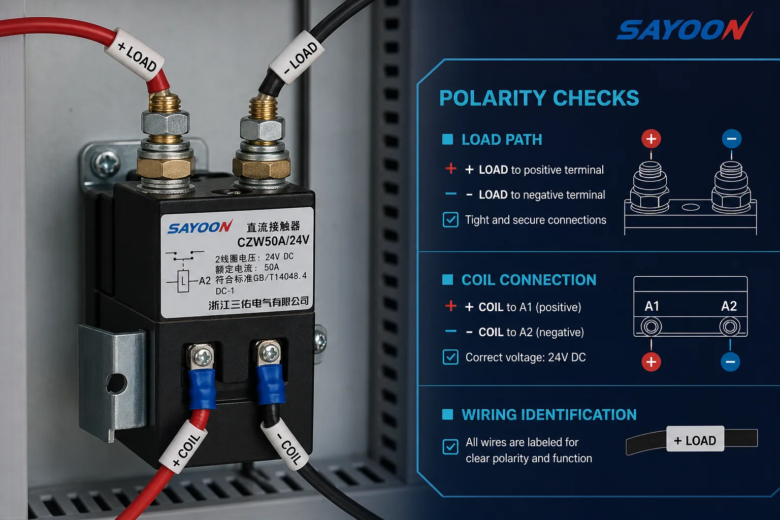
Solar and storage builders also debate charge versus discharge orientation of polar terminals. That debate belongs on the drawing as an explicit source/load note, not as a verbal instruction at the bench.
Auxiliary feedback the reviewer should see
Show each auxiliary contact’s resting state, terminals, and destination so auxiliary contact feedback is visible beyond the coil command.
An auxiliary contact is a mechanically linked low-current contact for status or interlock. It reports what the contactor did; it does not carry the main DC load.
OEM install sheets define a common rest-state rule: a normally open auxiliary is open when the contactor is de-energized, and a normally closed auxiliary is closed when de-energized. Mirror that language on the panel diagram.
Wire the aux destination on the sheet: PLC input, lamp, permissive, or hardwired interlock. A PLC that only issues a close command cannot see a welded main path without feedback.
On SZJB300A-D, an optional auxiliary switch can be ordered, with published optional ratings such as 2 A at 48 V DC or 5 A at 24 V DC in a 1NO 1NC arrangement. If the drawing needs that feedback, the aux option must appear on both the BOM and the schematic.
Labels and references that make the drawing reviewable
Add wire IDs, terminal marks, and document references so a second person can audit the DC contactor wiring diagram — the panel wiring diagram package — against the OEM drawing.
Skipping the manufacturer diagram because the device “looks familiar” is a recurring field mistake. The review package should name the project schematic revision and the model’s wiring figure.
Use consistent terminal language. Coil points may appear as A1/A2, L/A2, or color-coded leads depending on the family. Main studs need the same IDs used on the physical hardware.
Tag every control wire that leaves the contactor zone. Reviewers then compare the drawing to the harness without decoding tribal knowledge.
Browse the SAYOON products hub only after the six blocks above are filled. Product pages help match contact form and coil options; they do not replace the panel diagram.
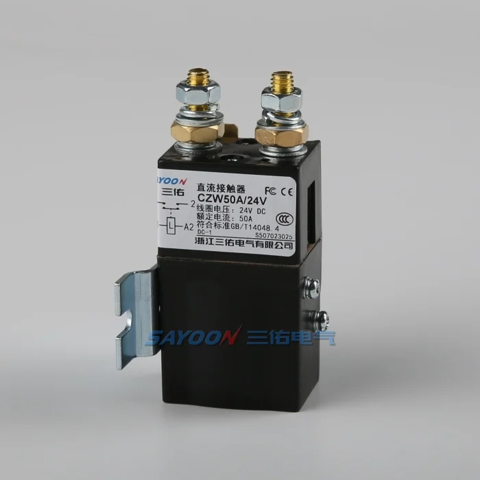
Select CZW50A when the diagram needs a 1 NO product fit
When the drawing needs a documented normally open low-voltage DC path, CZW50A is a concrete SAYOON example to open next.
The CZW50A normally open DC contactor publishes contact form 1 NO, coil voltage options such as 12 V, 24 V, 36 V, 48 V, 60 V, and 72 V, contact voltage ≤60 V, and a 50 A rated load current on a 48 V DC-1 circuit. It also publishes wiring and installation diagrams on the same page.
Match the drawing to that page in three steps:
- Confirm the main path is drawn as 1 NO at rest.
- Write the ordered coil voltage on the coil callout.
- Note suppressor-diode or auxiliary options if the BOM includes them.
If the panel instead needs a normally closed main path, review SZJB300A-D and its optional auxiliary switch against the same checklist. Do not force a 1 NO sketch onto a 1 NC requirement.
For family browsing after the contact form is locked, use the CZW series DC contactor hub or the SZJ series DC contactor hub.
ЧЗВ
Do DC contactor coils always need polarity marks on the diagram?
No. Mark polarity when the selected coil is polarized, dual-coil, PWM, or fitted with polarized suppression. Non-polarized coils still need voltage and terminal IDs.
What is the difference between main-contact polarity and coil polarity on the drawing?
Main-contact polarity orients marked power terminals to source and load for arc performance. Coil polarity orients the control leads so a polarized or economizer coil can operate safely.
Must auxiliary contacts appear even if the PLC already commands the coil?
Yes, when the design uses aux for feedback or interlocking. A coil command alone does not prove the main contacts followed.
Should coil suppression be drawn if it is built into the contactor?
Yes. Call out integral suppression so reviewers avoid adding a second path that changes dropout time or polarity rules.
How should NO vs NC main contact form be labeled for panel review?
State the resting state with the coil de-energized, using the same NO/NC language as the selected datasheet and product page.
What labels turn a sketch into a reviewable diagram?
Wire IDs, terminal marks that match the hardware, coil voltage, polarity notes where required, and references to the project schematic plus OEM wiring figure.
Does a capacitive DC load change what the diagram must show?
Often yes. Capacitance can require a pre-charge path and protection marks so the main contacts are not asked to close into an undocumented inrush.
Which SAYOON model fits a 1 NO low-voltage DC diagram example?
Start with CZW50A when the drawing needs a published 1 NO path, then confirm coil voltage and options against that product’s wiring diagram.
References
- Contactor Wiring Diagram: Power & PLC — independent technical overview of power versus coil circuits and auxiliary feedback.
- Are EV200 Contactor coil leads polarized — forum thread separating contact polarity from economizer coil polarity.
Humanizer audit: PASS
Second-pass check: no new facts, numbers, quotes, or citations were added beyond Research and Brief. Source-first and meta-process phrasing removed.





