Быстрый ответ: A BESS bidirectional contactor must carry charging and discharging current, but “bidirectional” also needs a precise switching definition. Confirm whether the device may make or break current in both directions, at the full DC voltage and actual circuit inductance. Then verify continuous thermal duty, precharge, fault coordination, coil control, auxiliary feedback, insulation, environment, and electrical endurance for every operating quadrant.
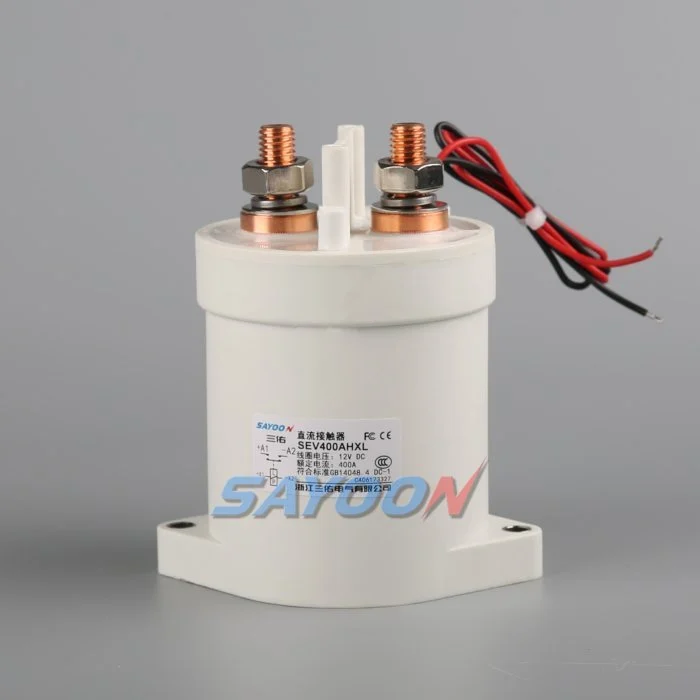
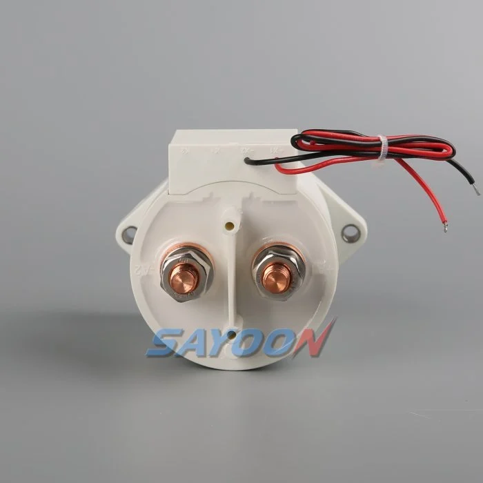
Настоящий путеводитель превращает эту тему в комплексный процесс проектирования, ввода в эксплуатацию и закупки оборудования BESS. В качестве визуального справочного материала использован реальный контактор Sayoon, при этом все характеристики, последовательности и решения по безопасности связаны с окончательной системой и текущей документацией производителя.
Карта инженерных решений
| Системное состояние | Ожидаемое состояние электричества | Концептуальный подход |
|---|---|---|
| Charge | PCS to battery | Continuous heating, charging limits, reverse current |
| Discharge | Battery to PCS | Peak current, bus sag, terminal temperature |
| Normal opening | Current reduced before opening | Residual current and DC arc direction |
| Emergency opening | Abnormal current in either direction | Qualified break duty and fuse coordination |
Ссылка на продукт и его область применения
Эт SEV400AHXL sealed high-voltage DC contactor является примером соответствующей реальной линейки продуктов. Проверьте Руководства высоковольтных токоприемников DC и Руководство по выбору контакторов постоянного тока для более широкого спектра рабочих процессов. Визуальный соответствие или номинальный ток не являются достаточными показателями для выбора модели для БЕС. Проверьте напряжение, текущий ток, рабочие характеристики, поляризацию, изоляцию, температуру, окружающую среду, срок службы, монтаж, конструкцию, драйвер и защиту вместе.
Define what bidirectional means
Current can flow toward the battery during charging and away from it during discharge. Carrying current in both directions is not the same as interrupting current in both directions. Internal magnetic arc control can make DC breaking performance polarity-sensitive even when the main terminals look symmetrical. Ask for explicit make and break data for each required direction, voltage, current, load type, and time constant.
Create an operating-state table that lists current direction at closure, during steady carry, and at opening. Include regeneration from the converter, charging from the grid, black-start behavior, DC-coupled generation, and maintenance tests. A state with nominally zero current should still specify a residual-current limit and how the controller verifies it.
Use maximum system voltage
Select against maximum charged battery voltage and defined transients, not only the nominal BESS label. The PCS can impose voltage during startup, shutdown, or a fault. Confirm which terminal may be positive in each state and whether the approved rating changes with polarity. Do not use an AC rating to infer DC interruption capability.
Insulation review covers dielectric strength, clearance, creepage, sealing, pollution, altitude, enclosure geometry, and distances to grounded metal. The completed assembly must be assessed because nearby busbars, sensors, and barriers change the effective insulation path.
Separate carry, make, and break duties
Continuous current drives I-squared-R heating. Make current depends on voltage difference, DC-link capacitance, precharge success, and circuit resistance. Break duty depends on current, voltage, inductance, polarity, contact opening, and protection action. A headline ampere rating does not combine these conditions. Use measured waveforms from charge and discharge operation.
List normal openings separately from emergency interruptions. Normal control should reduce PCS current before opening when the safety concept allows. Emergency duty may be limited to a small number of events, but it must still be supported by evidence and coordinated with the fuse or pyrofuse.
Check thermal performance in both modes
Charging and discharging may have different duration, RMS current, enclosure temperature, and cooling. Fast charging can create a long high-current period after a hot discharge. Model the full daily profile and validate it on production-intent busbars. Measure terminal and body temperatures after thermal stabilization.
Contact resistance, joint resistance, terminal torque, conductor size, surface condition, and neighboring components influence temperature. Use consistent four-wire voltage-drop points where practical. A device can meet average current yet exceed temperature limits during a stacked sequence of charge and discharge events.
Coordinate precharge and polarity
Precharge should reduce the voltage across the main contacts before closure. In a bidirectional system, either the battery or PCS side may be energized first, so the branch topology and resistor stress must be checked for both directions. Confirm blocking devices, sensing, and control logic prevent an unintended discharge through the precharge branch.
Authorize closure from measured voltage difference and stable polarity. Define the response to reversed sensor leads, a welded precharge contactor, open resistor, failed bus sensor, or externally energized PCS. Repeated failed attempts are counted in the duty profile.
Design feedback and fault logic
Auxiliary feedback reports mechanism position within its limits. Correlate it with command, coil current, pack-side voltage, bus-side voltage, and PCS current. If the commanded-open device still shows current or equalized voltage, investigate a weld, back-feed, sensor error, or parallel path. If commanded closed but current cannot flow, check the fuse, busbar, connection, and main path.
Store the first mismatch with direction, voltage, current, temperature, and timing. Avoid automatic retries when the system cannot prove an open state. Fault recovery should require controlled discharge and an explicit safe-state decision.
Validate interruption and protection
Calculate prospective fault current from battery strings and every parallel source. The contactor may only need to withstand current until the fuse clears, or it may be required to interrupt a defined current. These are different duties. Confirm the exact coordination, including current direction and available energy.
Test representative switching on production-intent hardware with the approved protection. Inspect contact resistance, timing, insulation, temperature, and physical condition before and after endurance blocks. A test at lower voltage or favorable polarity does not establish performance in the opposite quadrant.
Build the RFQ around waveforms
Provide minimum, nominal, maximum, and transient voltage; charge and discharge current traces; current at make and break; DC-link capacitance; circuit inductance; precharge; fault current; protection clearing; temperature; enclosure; altitude; vibration; mounting; busbars; coil voltage; driver; suppression; feedback; life; and required standards.
Request a drawing and product-specific evidence for both current directions. The SEV400AHXL shown here is a real product reference, not automatic approval for the application. Final selection requires the exact ordering code and verified duty.
Control changes through service life
Recheck the validated envelope when the battery configuration, PCS firmware, busbar, fuse, cooling, sensor, coil option, driver suppression, or daily operating profile changes. The contactor may look unchanged while make current, opening duty, temperature, release time, or insulation stress has changed. Compare revisions against a controlled baseline and repeat the affected calculations and tests.
During maintenance, inspect terminals, barriers, conductors, heat evidence, contamination, mounting, control wiring, and stored faults. Trend voltage drop and temperature only at comparable current and measurement points. After replacing a contactor, fuse, sensor, or controller, repeat the approved precharge, close, load, open, discharge, feedback, and restart-inhibit sequence before returning the rack to service.
Контроль за безопасностью и доказательствами
Обращайте аккумулятор, общие конденсаторы, преобразователи, параллельные резервные устройства и испытательное оборудование к источникам опасной энергии до тех пор, пока уполномоченное лицо не выполнит процедуру изоляции участка и не проверит необходимую работоспособность с помощью измерительных приборов. Не подключайте обратные провода, не пытайтесь закручивать катушки, не пытайтесь устранить замыкания высокого напряжения и не открывайте устройства, не соответствующие их назначению. СИЭО может оставаться в работоспособном состоянии в том случае, если его подключение происходит в направлении, которое не очевидно на упрощенной схеме.
Определите пределы приемлемости на основе точных данных о продукте, утвержденных системных требований и репрезентативных испытаний. Запишите полный код заказа, изменения чертежа, опции для катушек, карту выводов, расположение проводников, места установки приборов, калибровку, температуру, версию программного обеспечения, исходные сигнатуры, критерии прохождения/отрицания, отклонения и рецензентов. Отдельно фиксируйте измерения и их интерпретацию. Если отсутствует доказательная база, запишите открытую операцию, а не введите стандартную величину.
Связанные инженерные руководства
Используйте Руководство по размерам предохранительных резисторов, Руководство по достоверности отзывов контактных лиц, Руководство по стойкости к короткому замыканию, и Руководство по координации утепления как дополнительные проверки. Эти страницы охватывают различные решения и должны применяться к той же утвержденной границе системы.
Обучающее видео
A Look At High-Voltage EV Contactor Technology by CHARGED Electric Vehicles Magazine provides visual background on contactor operation and high-voltage switching. It does not replace the written design requirements or the product-specific validation.
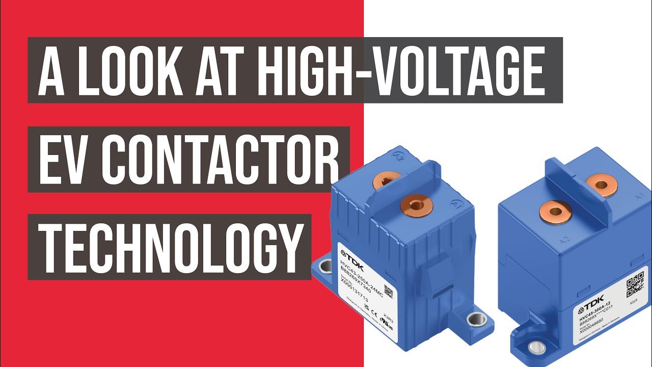
Посмотрите обучающее видео на YouTube.
Часто задаваемые вопросы
What is the first rule for bess bidirectional contactor?
Определите границы схемы и все источники питания, которые могут ее подавать питание, а затем проверьте точность работы устройств по измеренным параметрам напряжений и токов.
Может ли вспомогательная обратная связь подтвердить открытость основных контактов?
Нет. Сопоставьте вспомогательное состояние с напряжением на автобусе, током цепи, током катушки, временем и всеми возможными путями обратной подачей питания.
Необходимо ли заменить контактный элемент на шнуровой предохранитель?
Нет. Контактор обеспечивает контролируемое переключение, в то время как предохранитель обеспечивает защиту от перегрузки. Их характеристики в отношении стойкости и отключения должны быть согласованными.
Какие данные должны быть указаны в запросе на поставку оборудования BESS?
Включите диапазон напряжения, формы тока, режим работы «make and break», направление тока, предварительное наложение заряда, токовую утечку, защиту от перегрузок, температуру, монтаж, контроль катушки, обратную связь и целевой срок службы.
Авторитетные источники
- ОСХА 1910.147 — контроль опасной энергии
- ОСHA 1910.333 — практика электромонтажных работ
- IEC 60947-4-1 — контакторы и стартеры для электродвигателей
- Департамент энергетики США — энергохранение
Используйте принятые в рамках проекта издания и требования. Стандарты и данные о продукте могут измениться, поэтому ответственная инженерная команда должна подтвердить окончательный проект.





