Быстрый ответ: A BESS contactor spare-parts plan should be based on the installed population, failure consequence, supplier lead time, commonality, commissioning demand, service history, and shelf-control requirements. Stock complete, approved ordering codes with compatible coils, auxiliary arrangements, mounting, drivers, and ratings; include related fuses, sensors, connectors, hardware, and documentation where their absence would prevent a safe repair. A visually similar contactor is not an interchangeable spare.
This guide converts bess contactor spare parts into a practical engineering, commissioning, sourcing, and maintenance workflow. It uses authentic Sayoon product photography while keeping every approval tied to the final system, current documentation, applicable standards, and representative tests.
Decision checklist
| Зона обзора | Required record | Do not assume |
|---|---|---|
| Electrical boundary | One-line diagram and every energy source | An open command proves isolation |
| Exact hardware | Full ordering code, drawing, coil, feedback | Nominal current proves interchangeability |
| Limits | Source, uncertainty, margin, test evidence | A typical value applies to every BESS |
| Service response | Safe state, authorization, verification, restart | Clearing an alarm removes the cause |
Ссылка на продукт и границы его применения
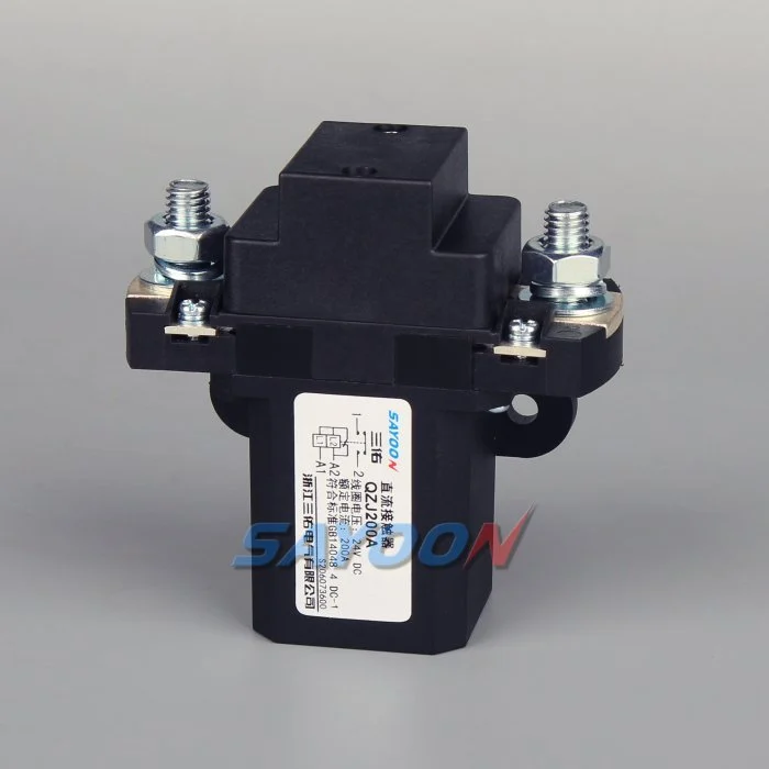
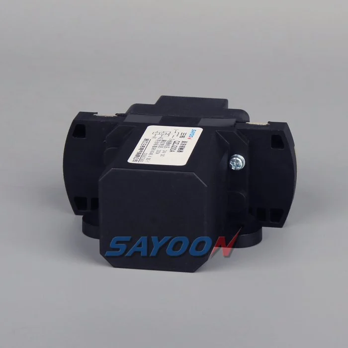
Эт Контактер постоянного тока нормально разомкнутый QZJ200A is a real product reference, not automatic approval for a BESS duty. Use the high-voltage DC contactor guide hub и selection guide for adjacent checks. Confirm the exact model, voltage, current waveform, make and break requirements, coil, feedback, insulation, environment, mounting, protection, and life.
Build the installed-base register
Create a register for every site and rack that records manufacturer, complete ordering code, serial or batch information where available, drawing revision, coil voltage, economizer or suppression, auxiliary contact arrangement, mounting, busbar interface, conductor hardware, fuse coordination, firmware dependency, and approved alternates.
Count active units, commissioning spares, field replacements, and units committed to other projects separately. Group only parts that engineering has proven interchangeable. Similar current labels can hide different voltage, break duty, polarity, coil behavior, terminal geometry, or feedback logic.
Set stock by consequence and replenishment
Estimate demand from the installed population, planned commissioning, preventive replacements, observed failure rate, diagnostic uncertainty, and damage during service. Then compare replenishment lead time with the maximum acceptable outage. Critical single-source parts and remote sites may justify more coverage than frequently available accessories.
Define minimum, reorder, and maximum levels with named owners. Review them after fleet growth, a supplier change, unusual failures, long lead-time movement, or an engineering change. Avoid turning an old revision into dead stock by buying quantity without configuration control.
Store, inspect, issue, and replenish
Keep spares in the supplier-specified temperature, humidity, orientation, packaging, and contamination controls. Protect terminals, leads, seals, labels, and mounting surfaces. Record receipt date, batch, location, inspection status, reservation, issue, return, and disposition. Use first-in-first-out only where shelf-life and revision rules allow it.
Before installation, verify identity, packaging condition, terminal condition, coil characteristics, auxiliary continuity as permitted, and required documents. After installation, complete the approved mechanical, insulation, coil, feedback, precharge, load, stop, and restart-inhibit checks. Quarantine suspect and removed parts until the failure review determines disposition.
Define the controlled boundary
Begin with a one-line diagram that identifies the battery string, positive and negative switching devices, precharge branch, common bus, converter, discharge path, fuses, sensors, service disconnects, and every possible back-feed source. Mark the exact boundary the contactors are expected to create. A command to open one device does not prove the service area is de-energized when another rack or converter remains connected.
List the operating states separately: storage, startup, precharge, closed, charge, discharge, normal stop, emergency stop, fault isolation, service, and restart. For each state record which devices are commanded, what voltage and current should exist on both sides, what feedback is required, and what response follows a disagreement.
Verify with independent evidence
Use command state, coil voltage or current, auxiliary feedback, main-circuit current, and pack-side and bus-side voltage as complementary evidence. The auxiliary contact reports mechanism position; it does not directly measure main-contact resistance or prove the absence of voltage. A timer proves elapsed time, not a safe electrical state.
Synchronize timestamps for commands, driver behavior, feedback transitions, current changes, and voltage response. Preserve the first mismatch and the raw data before retry logic changes the state. Define sensor plausibility checks and the response to a missing, frozen, saturated, or contradictory signal.
Set limits from the actual assembly
Do not copy a universal current, temperature, resistance, or timing threshold from an unrelated design. Establish limits from the exact contactor ordering code, coil option, driver and suppression, conductor geometry, fuse, enclosure, cooling, sensors, voltage, current waveform, ambient range, and required life.
Validate at low and high control supply, cold and hot conditions, the longest approved harness, and realistic charge and discharge profiles. Include measurement uncertainty and production variation. A nominal bench result without margin is not an acceptance limit.
Coordinate protection and controls
Contactors provide controlled switching, while fuses, breakers, or other protection devices address specified fault duties. Document which device acts first for each fault and what current the contactor must carry, withstand, or interrupt. Include contributions from parallel strings and the converter.
The controller should inhibit unsafe closure, manage precharge, verify closing, supervise operation, reduce current before normal opening when appropriate, confirm opening, and control discharge. For severe faults, follow the approved protection strategy rather than delaying action for a preferred software sequence.
Test failures, not only success
Fault-injection testing should cover low control voltage, open coil, shorted driver, stuck feedback, sensor loss, welded or stuck-open behavior, failed precharge, failed discharge, communications loss, cooling loss, and back-feed. Use approved simulators where creating a real hazardous fault is not acceptable.
Confirm the detected code, protective action, restart inhibit, operator message, retained data, and service procedure. Repeat important cases at environmental and supply boundaries. Record sample identity, drawing and software revisions, instruments, raw traces, acceptance criteria, deviations, and reviewers.
Plan safe service and restart
Treat batteries, DC-link capacitors, parallel racks, auxiliary supplies, and test equipment as hazardous energy sources until an authorized person has isolated them and verified the required condition with rated instruments. Do not bridge feedback, force a coil, or defeat an interlock to clear an alarm.
Resetting a fault or emergency device must not automatically re-energize the system. Require the initiating condition to clear, the approved inspection to finish, sensor and interlock checks to pass, isolation and discharge to be proven, and a deliberate authorized start command.
Control changes over the product life
Reopen the evidence when the battery configuration, converter firmware, busbar, cable, fuse, cooling, sensor, contactor, coil driver, suppression, enclosure, duty cycle, or maintenance interval changes. The assembly can look identical while switching, insulation, timing, or thermal stress has moved outside the validated envelope.
Track approved alternates by complete part number and revision. Keep drawings, supplier documents, incoming checks, commissioning records, trend data, failure reports, and corrective actions together so a future replacement can be evaluated against the original design basis.
For multi-site fleets, reserve stock against named outage scenarios rather than treating every warehouse unit as freely available. Define emergency transfer authority, transport packaging, customs documents, receiving checks, and the technician skills required at the destination. Keep a controlled replacement kit list covering approved fasteners, washers, labels, insulation barriers, connectors, and test records. Review whether a removed unit can be analyzed without consuming the only ready spare. A periodic tabletop exercise should prove that teams can identify the failed configuration, locate the correct stock, obtain approval, ship it, install it, complete validation, and replenish inventory within the stated recovery objective.
RFQ and evidence package
Provide the operating voltage range, normal and abnormal current waveforms, current direction, prospective fault current, upstream protection, coil supply, driver and suppression, auxiliary logic, environmental range, cooling, vibration, contamination, switching frequency, expected life, mounting and conductor arrangement, insulation requirements, monitoring inputs, diagnostic actions, and required approvals. Ask the supplier which claims apply to the exact order code and installation.
Separate calculations, supplier declarations, engineering assumptions, and measured validation results. Open questions must remain visible actions. Record who approved each limit, the source edition, sample identity, test equipment and calibration, raw results, deviations, and the conditions that trigger revalidation.
Связанные статьи Сайун
Review BESS main-contactor placement, parallel-string contactors, contactor feedback and fault logic, и DC-bus discharge after opening. These pages cover separate decisions that must agree in the final control and service strategy.
Обучающее видео
Что такое контактор и как он работает? by Electrician U is a useful visual refresher on contactor construction and operation. It does not replace product data, system calculations, standards, or site procedures.
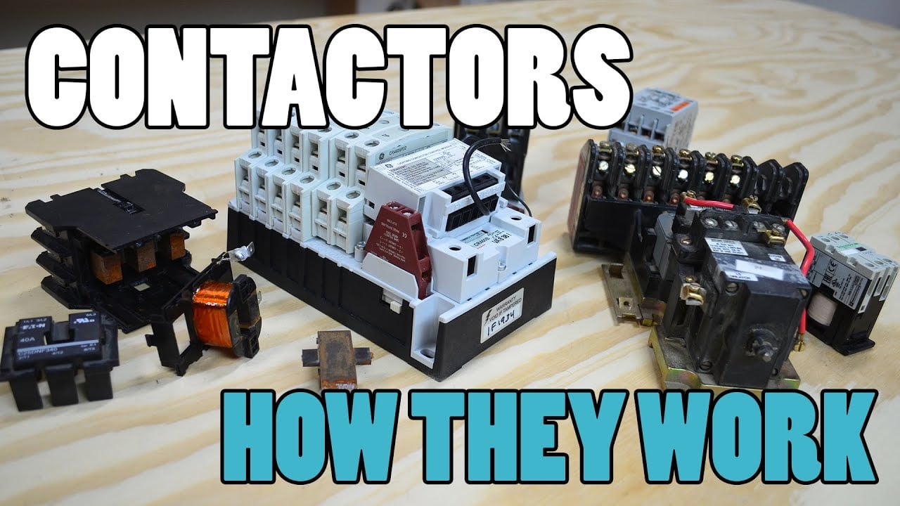
Посмотрите обучающее видео на YouTube.
Часто задаваемые вопросы
What is the first rule for bess contactor spare parts?
Define the exact system boundary, operating state, and evidence required before setting limits or taking action.
Can a similar contactor be substituted?
No. Engineering must confirm the complete ordering code, electrical duty, coil and driver, feedback, mounting, insulation, environment, protection, and validation evidence.
What data should be retained?
Keep commands, current, voltages, temperatures or insulation readings as applicable, timestamps, part identity, software and drawing revisions, test conditions, limits, deviations, and approvals.
When should the plan be reviewed?
Review it after a product, supplier, duty, wiring, cooling, firmware, protection, failure trend, or maintenance-process change.
Авторитетные источники
- ОСХА 1910.147 — контроль опасной энергии
- ОСHA 1910.333 — практика электромонтажных работ
- IEC 60947-4-1 — контакторы и стартеры для электродвигателей
- Департамент энергетики США — энергохранение
Use the standards and editions adopted by the project, and confirm current requirements before final approval.





